Drawing apparatus, and method of manufacturing article

Active Publication Date: 2015-01-01
CANON KK
View PDF8 Cites 0 Cited by
  • Summary
  • Abstract
  • Description
  • Claims
  • Application Information

AI Technical Summary

Benefits of technology

The present invention provides a drawing apparatus that can use common drawing data with multiple charged particle optical systems. The apparatus includes a storage component that stores the shared drawing data, and a controller that determines the drawing region on a substrate and controls each charged particle optical system based on a set of sub-drawing regions. The technical effect of this invention is to enable more efficient use of drawing data and to improve the accuracy and precision of charged particle beam drawing.

Problems solved by technology

In this case, it may be impossible to share the drawing data.
This is disadvantageous in reducing the scale of drawing data to be handled in parallel and enhancing throughput.

Method used


Image

  • Drawing apparatus, and method of manufacturing article
  • Drawing apparatus, and method of manufacturing article
  • Drawing apparatus, and method of manufacturing article

Examples


first embodiment

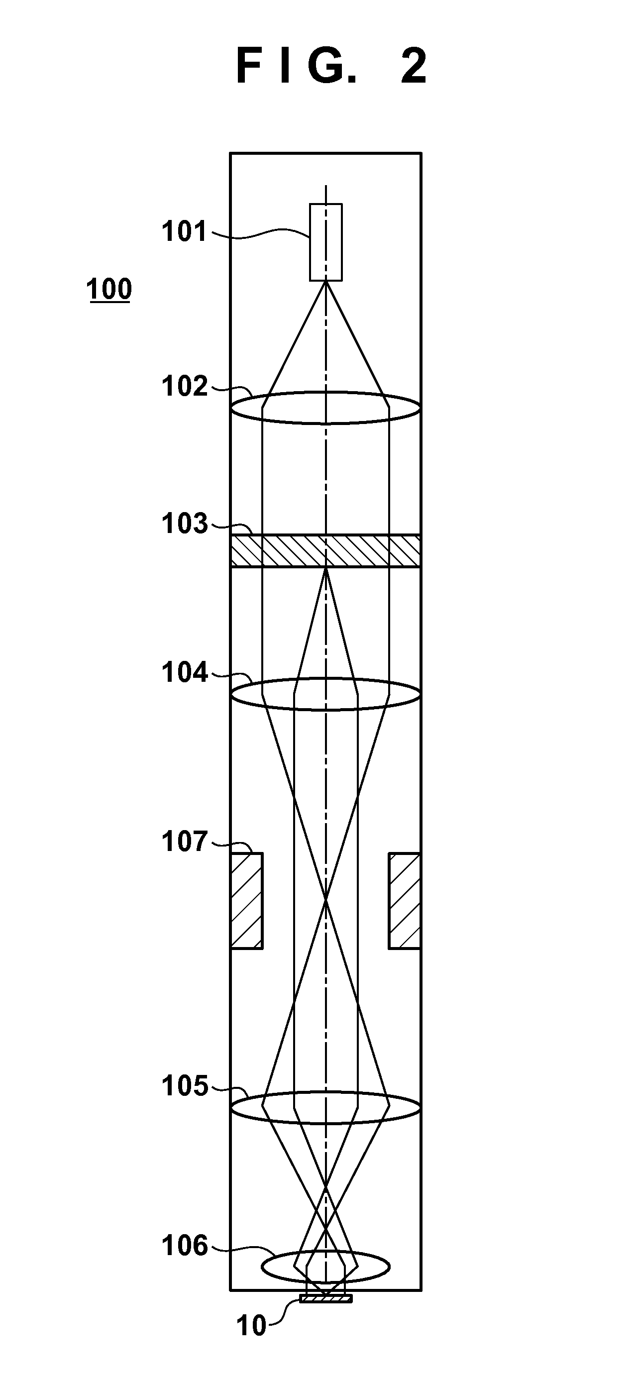
[0019]FIG. 2 is a view showing the arrangement of a plurality of electron optical systems (charged particle optical systems) 100 included in a drawing apparatus of the present invention. An electron source 101 is a so-called thermoelectron (thermal electron) emission electron source including, for example, LaB6 or BaO / W (dispenser cathode) as an electron emitting material. A collimator lens 102 is, for example, an electrostatic lens configured to converge an electron beam by an electric field. An electron beam emitted by the electron source 101 changes to an almost parallel electron beam via the collimator lens 102.

[0020]A blanking aperture array 103 divides the almost parallel electron beam from the collimator lens 102 into a plurality of electron beams by two-dimensionally arrayed apertures (not shown). Irradiation of a wafer (substrate) 10 of the electron optical system 100 with the plurality of divided electron beams is on-off-controlled by an individually drivable electrostatic...

second embodiment

[0031]When a width Ws of the shot region is not an integer multiple of a width βWd of the drawing region, the drawing regions are different for the respective shot regions in an alignment direction of the drawing regions even in one electron optical system, as in FIG. 5B showing the first embodiment. In the second embodiment, however, the drawing regions are identical for the respective shot regions in the alignment direction of the drawing regions in one electron optical system.

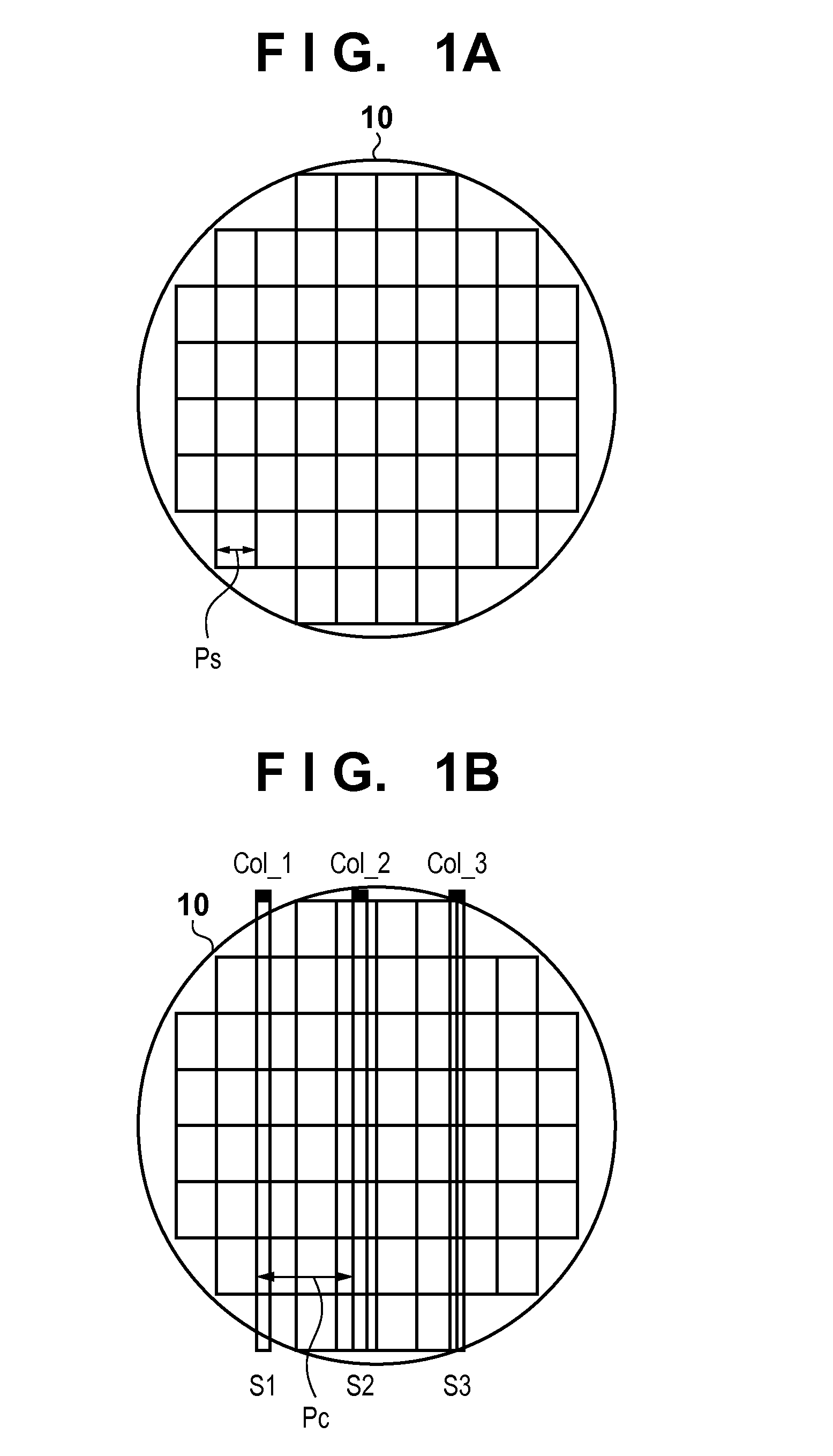
[0032]A generation process and a drawing method of the drawing data will be described with reference to FIGS. 6A to 6D. FIGS. 6A And 6B show a state of drawing by a first electron optical system Col_1. When a drawing apparatus starts drawing, a main controller 21 generates data of drawing regions S1_1 to S1_4 for drawing the first shot region so that, as shown in FIG. 6A, the left edge of the first shot region matches that of the first drawing region S1_1. The first electron optical system Col_1 draws the dr...

third embodiment

[0037]Since a drawing pattern may be divided due to a drawing positional shift between the drawing regions in the first and the second embodiments, multiple drawing is typically performed by making the drawing regions overlap each other. Hence, as shown in FIG. 7, data of a stitching region on the partial region basis may be added to the edge of drawing data on the drawing region basis.


PUM


Abstract

A drawing apparatus includes: a plurality of charged particle optical systems arranged along a first direction; a storage configured to store drawing data shared by the plurality of charged particle optical systems with respect to each of sub-drawing regions obtained by dividing a drawing region on the substrate of each of the plurality of charged particle optical systems in the first direction; and a controller configured to determine a drawing region on the substrate by each of the plurality of charged particle optical systems as a set of the sub-drawing regions and control each of the plurality of charged particle optical systems based on a corresponding set of the sub-drawing regions.

Description

BACKGROUND OF THE INVENTION[0001]1. Field of the Invention[0002]The present invention relates to a drawing apparatus, and a method of manufacturing an article.[0003]2. Description of the Related Art[0004]As a drawing apparatus used to manufacture a device such as a semiconductor integrated circuit, Japanese Patent Laid-Open No. 2005-129944 proposes a drawing apparatus that performs drawing simultaneously on a plurality of shot regions of a substrate using a plurality of electron optical systems (charged particle optical systems).[0005]When using the drawing apparatus described in Japanese Patent Laid-Open No. 2005-129944, if the plurality of electron optical systems draw identical (corresponding) places in the different shot regions, drawing data used by the plurality of electron optical systems can be shared. This makes it possible to reduce the scale of drawing data to be held and handled. Moreover, if the electron optical systems have almost identical regions such as dicing line ...

Claims


Application Information

Patent Timeline
IPC IPC(8): H01J37/30H01J37/20
CPCH01J37/20H01J37/3007H01J2237/31764H01J37/3177H01J37/3026
Inventor MURAKI, MASATOTSUCHIYA, GO
Owner CANON KK
Why Eureka
Try Eureka