Check valve for injecting gas

a check valve and gas injection technology, which is applied in the direction of valve housings, valve operating means/release devices, machines/engines, etc., can solve the problems of uncombusted gas flowing backward through the gap, the opening/closing of the check valve is not smoothly performed, etc., and achieves the effect of improving productivity, smooth gas injection, and short tim

Active Publication Date: 2015-01-01
HYUNDAI HEAVY IND CO LTD
View PDF31 Cites 8 Cited by
  • Summary
  • Abstract
  • Description
  • Claims
  • Application Information

AI Technical Summary

Benefits of technology

[0022]As described above, in a check valve for injecting gas according to the embodiment of the present invention, since a corrugated portion is provided on each of an outer surface of a body and an outer surface of a spindle, the corrugated portion on the outer surface of the body provides a gas flow space so that gas injection can be smoothly performed.
[0023]Also, in the check valve for injecting gas according to the embodiment of the present invention, the body and the spindle are individually integrally formed so that the number of parts can be minimized, disassembly and assembly can be conveniently performed with a short time and productivity can be improved.
[0024]In addition, in the check valve for injecting gas according to the embodiment of the present invention, deformation of a lower end portion of the body is prevented by a spacer so that uncombusted gas can be prevented from flowing backward due to deformation of the lower end portion of the body.
[0025]Furthermore, the check valve for injecting gas according to the embodiment of the present invention is supported and driven through an outer surface of a spring seat and an inner surface of a coupling ring so that friction between members of the check valve can be reduced and durability can be enhanced.

Problems solved by technology

In this case, since carbon is fixed to the check valve for injecting gas, opening / closing of the check valve is not smoothly performed, or opening / closing of the check valve itself is not performed.
However, since the check valve mounting portion is narrow, even when the check valve 100′ is installed to be slightly twisted, a gap is formed in a check valve seat portion in which the body 110′ of the check valve 100′ and a circumference of a lower end of a spindle 120′ contact each other, such that uncombusted gas may flow backward through the gap.

Method used


Image

  • Check valve for injecting gas
  • Check valve for injecting gas
  • Check valve for injecting gas

Examples


Embodiment Construction

[0037]Hereinafter, exemplary embodiments of the present invention will be described in detail.

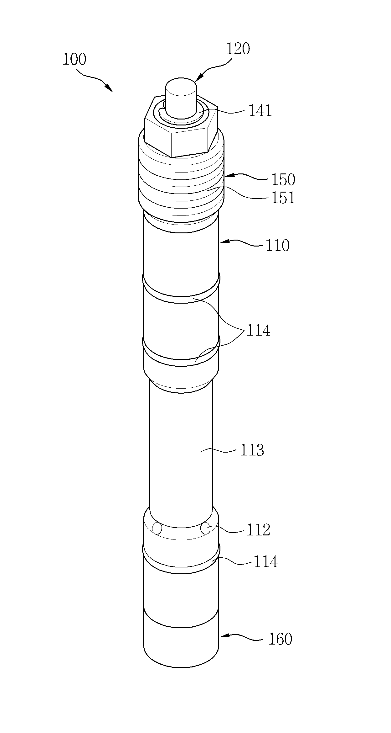
[0038]As illustrated in FIGS. 3 and 4, a check valve 100 for injecting gas according to an exemplary embodiment of the present invention includes a body 110, a spindle 120, a spring 130, a spring seat 140, a coupling ring 150, and a spacer 160.

[0039]The body 110 includes a corrugated portion 113 that is provided on an outer surface of an upper portion of a gas flow hole 112 and has a smaller diameter than diameters of other portions.

[0040]The body 110 may be integrally formed.

[0041]The body 110 is integrally formed so that the number of parts can be minimized.

[0042]The gas flow hole 112 of the body 110 may extend in all directions.

[0043]The gas flow hole 112 of the body 110 extends in all directions so that gas inflow through the gas flow hole 112 can be uniformly performed regardless of a direction.

[0044]A sealing 114 may be continuously coupled to an outer surface of the body 110 at verti...


PUM


Abstract

A check vale for injecting gas comprises: an integrally formed body provided with a corrugated portion having a diameter smaller than other areas on an outer surface of an upper portion of a gas flow hole; an integrally formed spindle perpendicularly penetrating the body and provided with a corrugated portion having a diameter smaller than other areas on an outer surface of a lower portion of the gas flow hole of the body; a spring penetrating an upper end portion of the spindle; a spring seat for fixing the spring penetrating the upper end portion of the spindle and for guiding the spindle to a perpendicular position; a coupling ring coupled to an upper end of the body for fixing the body to a prechamber; and a spacer coupled to a lower end of the body for fixing the lower end of the body that covers an outer edge of the spindle to the prechamber.

Description

TECHNICAL FIELD[0001]The present invention relates to a check valve for injecting gas, and more particularly, to a check valve for injecting gas, which enables smooth injection of gas, improved productivity by allowing quick and simple disassembly and assembly, an increased usage life by providing enhanced durability by means of minimizing abrasion of main parts, and prevention of backflow of uncombusted gas.BACKGROUND ART[0002]Gas injection is performed in a precombustion chamber of a gas engine in accordance with an operation of a check valve for injecting gas.[0003]In this case, types of the check valve for injecting gas include a ball type, a plate type, and a poppet type. These types of the check valve for injecting gas are selectively applied according to conditions due to their advantages or disadvantages.[0004]Combustion of gas having a heavy mixed concentration in which air and gas are mixed with each other near a theoretical air-fuel ratio, is performed so that carbon can ...

Claims


Application Information

Patent Timeline
Patent Type & Authority Applications(United States)
IPC IPC(8): F16K31/44F16K3/24F02M61/20
CPCF02M61/20F16K31/44F16K3/24F02M21/0251F02B19/108F02M21/0275F02M21/0269F02B19/12Y02T10/125F16K31/485Y02T10/32F02M21/0242Y02T10/12Y02T10/30F16K27/0209F01L3/08
Inventor LEE, DAE-JINJUNG, DAE-YEOULKIM, SUNG-HYEOKHEO, KWANG-CHEOLKIM, JONG-SUK
Owner HYUNDAI HEAVY IND CO LTD
Why Eureka
Try Eureka