Power Supply Device Using Secondary Battery and Method of Switching the Battery Mode

Active Publication Date: 2015-01-01
JU JINGWAN
View PDF11 Cites 13 Cited by
  • Summary
  • Abstract
  • Description
  • Claims
  • Application Information

AI Technical Summary

Benefits of technology

[0051]According to the solving means of the above problems, more than two secondary batteries are employing that; most power of the discharging secondary battery supplies to load, and rest of the output is used to charge another secondary battery. Therefore, it is possible to improve the battery efficiency and prolong the usable time (discharge time) of the secondary battery. Thus, the suitable control device for power supplying and control method has developed by using the secondary battery cells.
[0052

Problems solved by technology

While the secondary battery is charging, it is impossible to discharging or the efficiency of charging-discharging is significantly diminished.
Furthermore, in case of this secondary battery is continuously used to discharge the normal rated current, it is a common problem that the actual using time of this secondary battery is markedly shortened than the ideal using time set by manufacturer.
Thus, there is a problem that due to the declined efficiency of the secondary lead battery, the battery usable time as fully charged state (discharging time) will be significantly shortened.
On the other hand, the number of charging/discharging cycles of the secondary battery has limited.
As an examp

Method used


Image

  • Power Supply Device Using Secondary Battery and Method of Switching the Battery Mode
  • Power Supply Device Using Secondary Battery and Method of Switching the Battery Mode
  • Power Supply Device Using Secondary Battery and Method of Switching the Battery Mode

Examples


Embodiment Construction

[0065]Hereinafter, the configuration and operation of the preferred embodiment of the present invention will be described in detail with reference to the accompanying drawings.

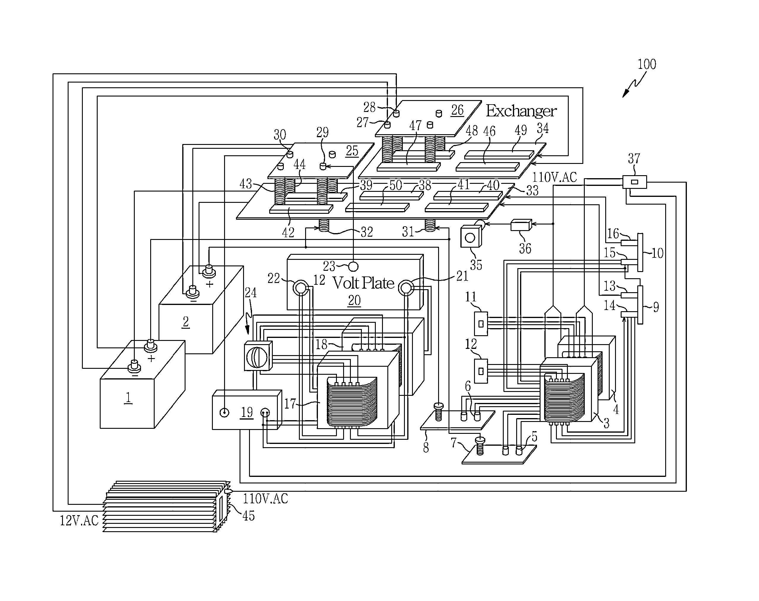
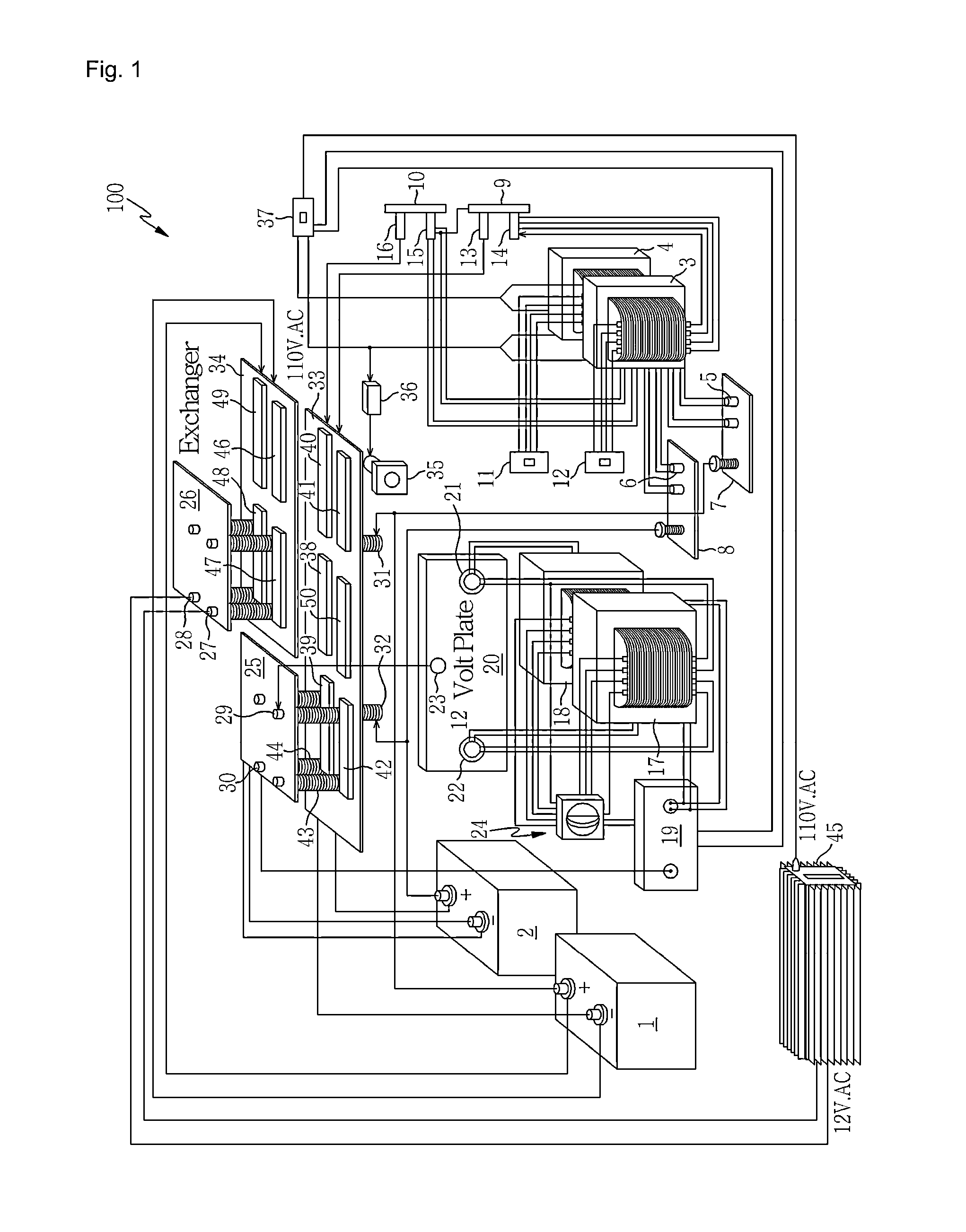
[0066]FIG. 4 is an overall configuration of the power supply apparatus according to the present invention. FIG. 5 is a perspective photograph showing the relay front view of the FIG. 1. FIG. 6 is a perspective photograph showing the relay rear view of the FIG. 1. FIG. 7 is a photograph showing the relay lateral view of the FIG. 1. FIG. 8 is a partial cross-sectional view of the relay of the FIG. 1. FIG. 9 is a controller circuit diagram of the FIG. 1. FIG. 10 is a flow chart showing the controller operation of the FIG. 9. FIG. 11a is a photograph showing discharging state of the battery 1 as a power source device and displaying the actual charging status of the battery 2 of the present invention. FIG. 11b is a photograph showing discharging state of the battery 2 as a power source device and displaying the act...


PUM


Abstract

The present invention employs more than two secondary batteries; most output of one battery is supplied to load, and rest output is used to charge another battery for improving the battery efficiency and prolong the battery usable time (discharge time). The object of the present invention is to provide a power supplying device and battery mode switching method by using the secondary battery cells. According to the present invention of using more than two secondary batteries that; if either one of the secondary battery sets for discharging mode, the device including that; an inverter for delivering a DC output voltage of the secondary battery, which is in discharging mode, when one of the more than two secondary batteries is discharged; a relay performing the switching operation for connecting to other different secondary battery of more than two secondary batteries to the inverter, at other point, the secondary battery in discharge mode of more than two secondary battery is connected to the inverter; and a controlling unit for alternately supping the power of the more than two or secondary batteries to the load by controlling the switching operation of the relay via the inverter, a switching unit alters charging or discharging mode, the anode (+) and cathode (−) of each DC terminal, which is mutually and fixedly connected, and each moveable terminal of the secondary battery is switched to control the battery mode.

Description

BACKGROUND OF THE INVENTION[0001]1. Field of the Invention[0002]The present invention relates to a power supply device utilizing the secondary battery and method of switching the battery mode. Particularly, more than two secondary batteries are employed; one secondary battery is used for supplying the output power to the load, while other secondary battery is used to charge at least one battery at the same time, so that it is possible to improve the energy efficiency.[0003]2. Related Prior Art[0004]Unlike the primary battery, which is disposed after used-up once, generally the secondary battery is rechargeable through the reversible reaction, when it will be discharged.[0005]However, such a secondary battery should be charged again by charging capacity of the battery after a certain time has elapsed, when it is discharged. While the secondary battery is charging, it is impossible to discharging or the efficiency of charging-discharging is significantly diminished. In most cases, mor...

Claims


Application Information

Patent Timeline
IPC IPC(8): H02J7/02H02J7/00
CPCH02J7/0068H02J7/022H02J7/007H02J7/0047H02J7/0013H02J7/35H02J2207/40H02J2207/20H02J7/342H02J7/02H02J7/0025H02J7/0048H02J7/04H02J7/00
Inventor JU, JINGWAN
Owner JU JINGWAN
Why Eureka
Try Eureka