System and Method for a Transformer and a Phase-Shift Network

a phase-shift network and transformer technology, applied in the field of electronic devices, can solve the problems of difficult construction of stripline directional couplers on integrated circuits, and the difficulty of low-loss magnetic-based directional couplers

Active Publication Date: 2015-01-01
INFINEON TECH AG
View PDF13 Cites 17 Cited by
  • Summary
  • Abstract
  • Description
  • Claims
  • Application Information

AI Technical Summary

Problems solved by technology

For applications that operate at frequencies between 500 MHz and 3 GHz, which covers the frequency range at which many cellular telephones operate, constructing stripline directional couplers on an integrated circuit becomes challenging dues to the wa

Method used


Image

  • System and Method for a Transformer and a Phase-Shift Network
  • System and Method for a Transformer and a Phase-Shift Network
  • System and Method for a Transformer and a Phase-Shift Network

Examples


Embodiment Construction

[0015]The making and using of the presently preferred embodiments are discussed in detail below. It should be appreciated, however, that the present invention provides many applicable inventive concepts that can be embodied in a wide variety of specific contexts. The specific embodiments discussed are merely illustrative of specific ways to make and use the invention, and do not limit the scope of the invention.

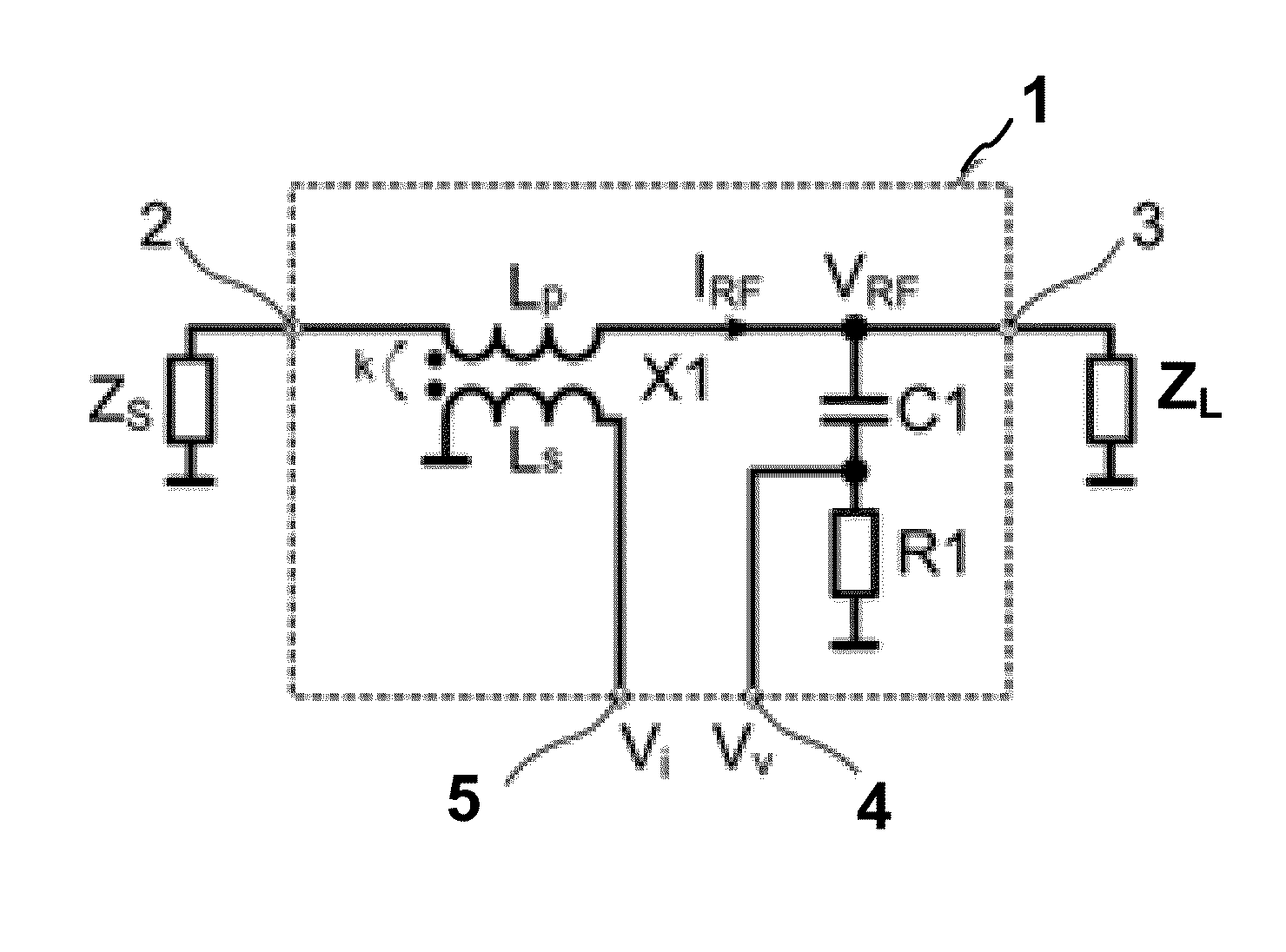
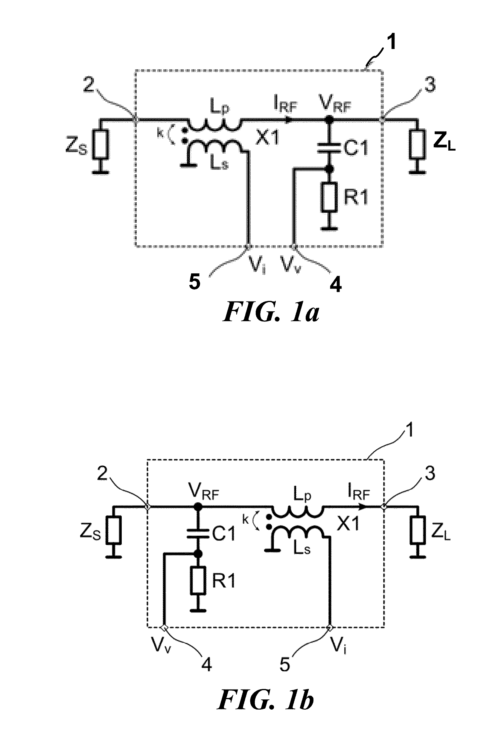
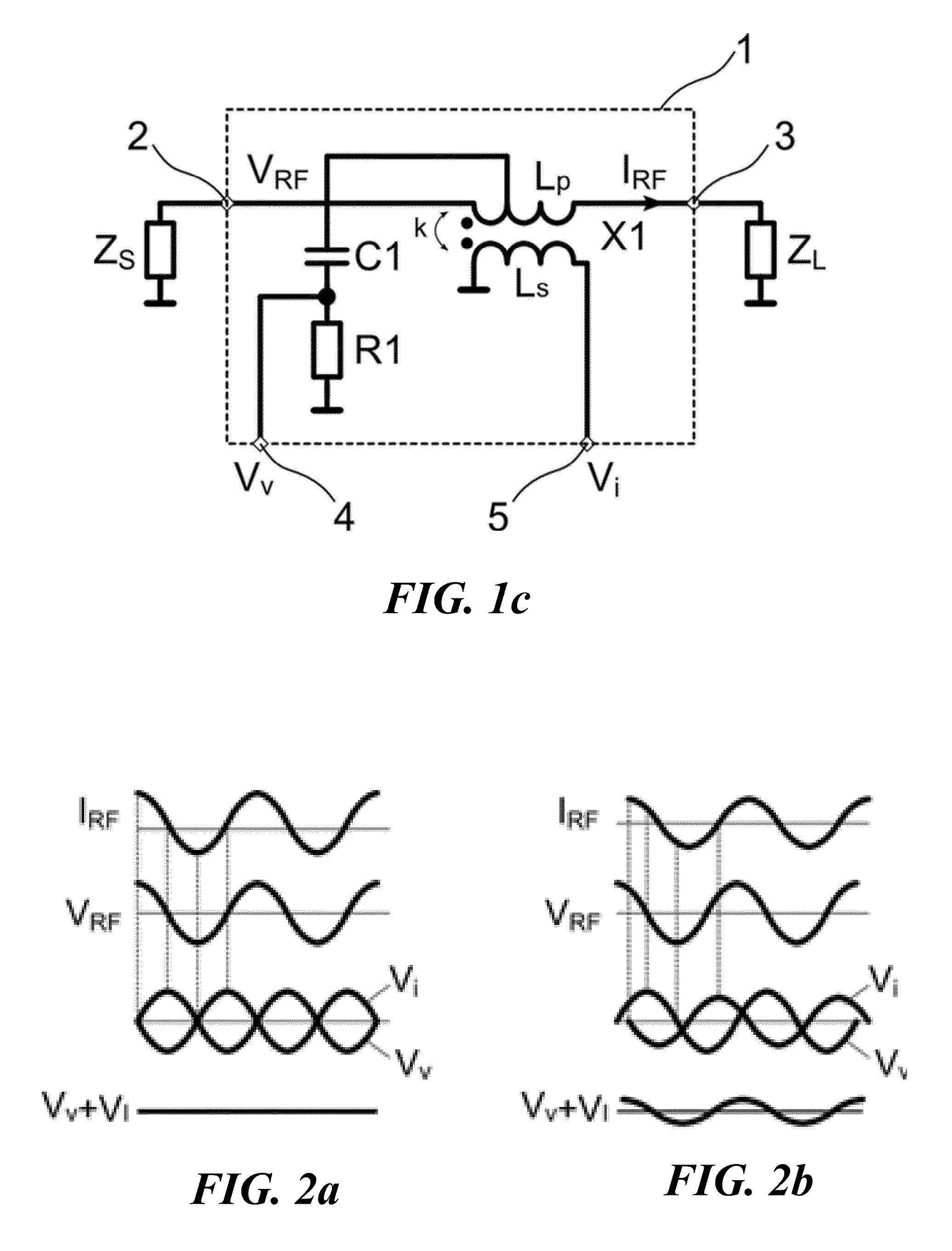
[0016]The present invention will be described with respect to preferred embodiments in a specific context, a system and method for a directional coupler that may be used in RF circuits to measure incident or reflected power. The invention may also be applied to other systems and applications including other circuits that make RF measurements including, but not limited to devices that measure and / or tune impedance mismatch, time domain reflectometers (TDR), sensing devices for use with tunable antenna matching circuits, and tunable filters.

[0017]In an embodiment of the present...


PUM


Abstract

In accordance with an embodiment, a circuit includes a magnetic transformer having a first winding coupled between a first signal node and a second signal node, and a second winding coupled between a first reference node and a current measurement node. A phase shift network is coupled between the second node and a voltage measurement node, and the circuit is configured to indicate an impedance matching condition based on an amplitude difference and a phase difference between the voltage measurement node and the current measurement node.

Description

TECHNICAL FIELD[0001]The present disclosure relates generally to an electronic device, and more particularly to a system and method for a transformer and a phase-shift network.BACKGROUND[0002]Directional couplers, which are electronic devices that can detect power being transmitted in a particular direction, are used in a wide variety of radio frequency (RF) circuits. For example, a directional coupler may be used in a radar system to detect a reflected wave by separating the indecent wave from the reflected wave, or may be used in a circuit that measures the impedance mismatch of transmission lines. Functionally, a directional coupler has a forward transmission path and a coupled transmission path. The forward transmission path generally has a low loss, while the coupled transmission path couples a fraction of the transmission power that is propagated in a particular direction. There are many different types of coupler architectures that include electromagnetic couples and magnetic...

Claims


Application Information

Patent Timeline
IPC IPC(8): G01R33/09
CPCG01R33/09H03H7/18H03H7/40
Inventor SOLOMKO, VALENTYNBAKALSKI, WINFRIED
Owner INFINEON TECH AG
Why Eureka
Try Eureka