Control circuit for active-clamp flyback power converter with programmable switching period

a control circuit and power converter technology, applied in the direction of electric variable regulation, process and machine control, instruments, etc., can solve the problems of higher power loss problem, active-clamp circuit can only achieve zero-voltage switching, etc., and achieve high-efficiency effects

Active Publication Date: 2015-01-01
SEMICON COMPONENTS IND LLC
View PDF10 Cites 65 Cited by
  • Summary
  • Abstract
  • Description
  • Claims
  • Application Information

AI Technical Summary

Benefits of technology

[0006]The present invention proposes a control circuit for active-clamp flyback power converter. It can achieve zero-voltage switching at heavy load and achieve high-efficiency at the light load. The objective of the present invention is to provide a method and approach to ensure the active-clamp flyback power converter can achieve zero-voltage switching at heavy-load condition and can achieve high-efficiency during light-load condition.

Problems solved by technology

The traditional active-clamp circuit can only achieve zero-voltage switching at particular load condition.
Besides, its high circulated current during light-load condition causes higher power loss problem.

Method used


Image

  • Control circuit for active-clamp flyback power converter with programmable switching period
  • Control circuit for active-clamp flyback power converter with programmable switching period
  • Control circuit for active-clamp flyback power converter with programmable switching period

Examples


Embodiment Construction

[0024]The following description is of the best-contemplated mode of carrying out the invention. This description is made for the purpose of illustrating the general principles of the invention and should not be taken in a limiting sense. The scope of the invention is best determined by reference to the appended claims.

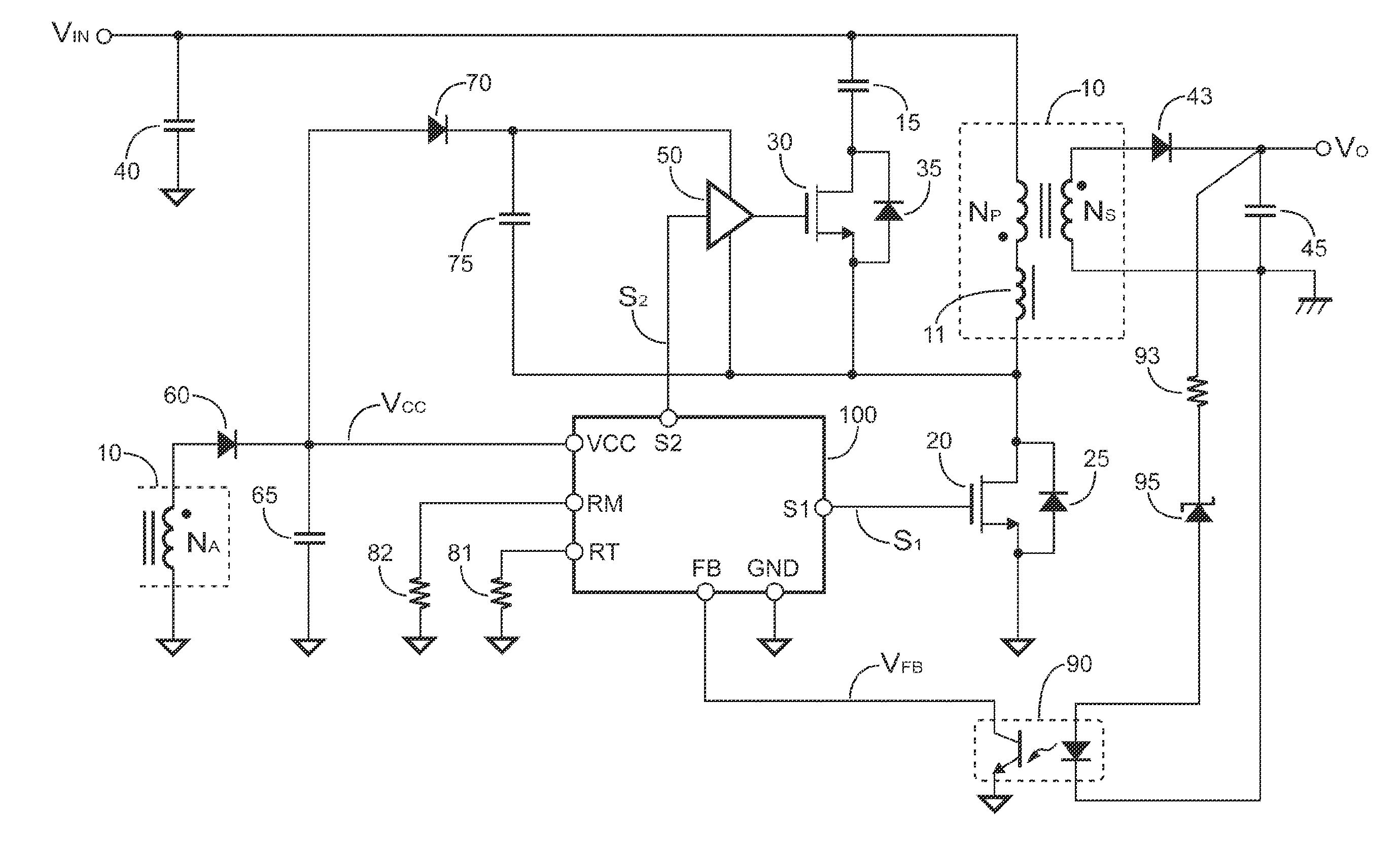
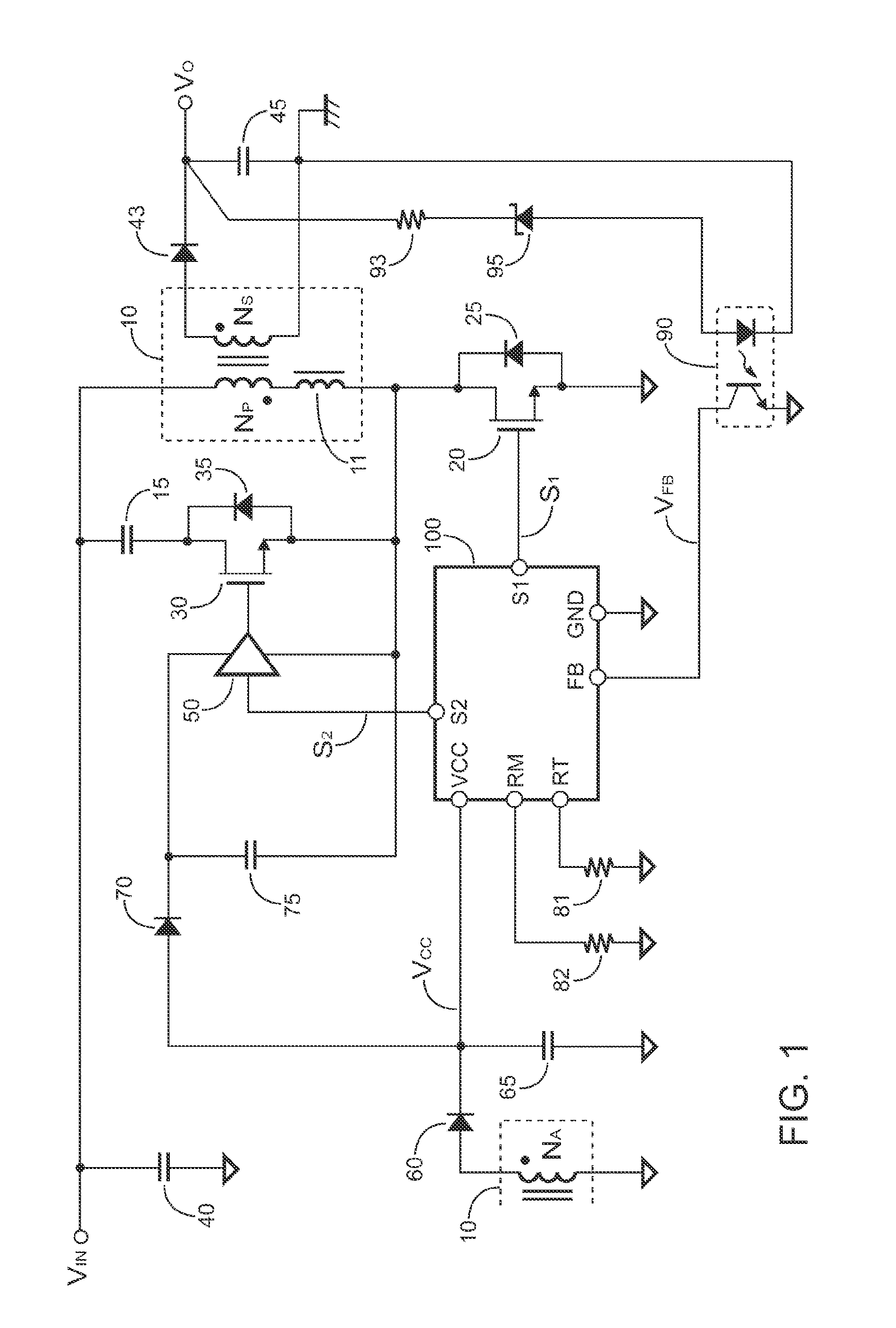
[0025]FIG. 1 shows an exemplary embodiment of a flyback power converter according to the present invention. A transformer 10 is coupled to receive an input voltage VIN of the power converter. A transistor (also referred to as “low-side transistor”) 20 is coupled to switch a primary winding NP of the transformer 10. A controller 100 generates a switching signal S1 at a terminal S1, and the switching signal S1 is coupled to drive the transistor 20 for regulating an output voltage VO of the power converter. The switching signal S1 is generated in response to a feedback signal VFB at a terminal FB of the controller 100. The feedback signal VFB is correlated to the output v...


PUM


Abstract

A method for controlling an active-clamp flyback power converter is provided. The method includes comprises: generating a switching signal in response to a feedback signal for switching a low-side transistor and regulating an output of the active-clamp flyback power converter; generating an active-clamp signal after the switching signal is disabled; generating a hysteresis bias to adjust the feedback signal; and generating a pulse signal periodically to enable the switching signal. The low-side transistor is coupled to switch a transformer. The switching signal is coupled to drive the low-side transistor. The active-clamp signal is coupled to drive a high-side transistor. A pulse width of the active-clamp signal is determined by a first resistor. The high-side transistor is connected in series with a capacitor to develop an active-clamp circuit. A minimum frequency of the switching signal is determined by a second resistor during a heavy load condition.

Description

CROSS REFERENCE TO RELATED APPLICATIONS[0001]This application claims the benefit of U.S. Provisional Application No. 61 / 840,073, filed on Jun. 27, 2013, the contents of which are incorporated herein by reference.BACKGROUND OF THE INVENTION[0002]1. Field of the Invention[0003]The present invention relates to an active-clamp flyback power converter, and, more specifically, the present invention relates to a control circuit of the active-clamp flyback power converter.[0004]2. Description of the Related Art[0005]The traditional active-clamp circuit can only achieve zero-voltage switching at particular load condition. Besides, its high circulated current during light-load condition causes higher power loss problem. The related prior arts can be found in “Clamped Continuous Flyback Power Converter”, U.S. Pat. No. 5,570,278; “Offset Resonance Zero Voltage Switching Flyback Converter” U.S. Pat. No. 6,069,803 and “Active-clamp Circuit for Quasi-resonant Flyback Power Converter”, U.S. patent ...

Claims


Application Information

Patent Timeline
Patent Type & Authority Applications(United States)
IPC IPC(8): H02M3/335
CPCH02M3/33507H02M3/33569H02M2001/342H02M3/33523Y02B70/10H02M1/0006H02M1/342H02M3/01
Inventor YANG, TA-YUNGLIU, YEN-MING
Owner SEMICON COMPONENTS IND LLC
Why Eureka
Try Eureka