Multilevel power conversion circuit

a power conversion circuit and multi-level technology, applied in power conversion systems, emergency protective circuit arrangements, electrical equipment, etc., can solve the problems of secondary damage, diodes, capacitors, and capacitors being broken down as secondary damages, and it is difficult to solve secondary damage problems, so as to achieve the effect of safe stopping

Inactive Publication Date: 2015-01-01
FUJI ELECTRIC CO LTD
View PDF17 Cites 21 Cited by
  • Summary
  • Abstract
  • Description
  • Claims
  • Application Information

AI Technical Summary

Benefits of technology

[0026]In some embodiments, a multilevel power conversion circuit using a flying capacitor comprises at least two semiconductor switching devices composing bidirectional switches connected to a middle potential terminal of DC power supplies, the semiconductor switching devices being connected in series in the same current flowing direction. Short-circuit fault of one of the semiconductor switching devices composing the bidirectional switches is detected to stop the power conversion system. Consequently, when one of the semiconductor switching devices composing the bidirectional switches suffers short-circuit fault, the system can be safely stopped without breaking other semiconductor switches and capacitors.

Problems solved by technology

Thus, the IGBT, diode, and the capacitor may be broken down as secondary damages.
The secondary damages could be avoided by raising the voltage ratings of the IGBT and diode composing the semiconductor switch and the capacitor, which however causes cost rise.
In addition, because the inductance of a load cannot be known in advance, it is practically difficult to solve the problem of secondary damages by preliminary design.

Method used


Image

  • Multilevel power conversion circuit
  • Multilevel power conversion circuit
  • Multilevel power conversion circuit

Examples


embodiment example 1

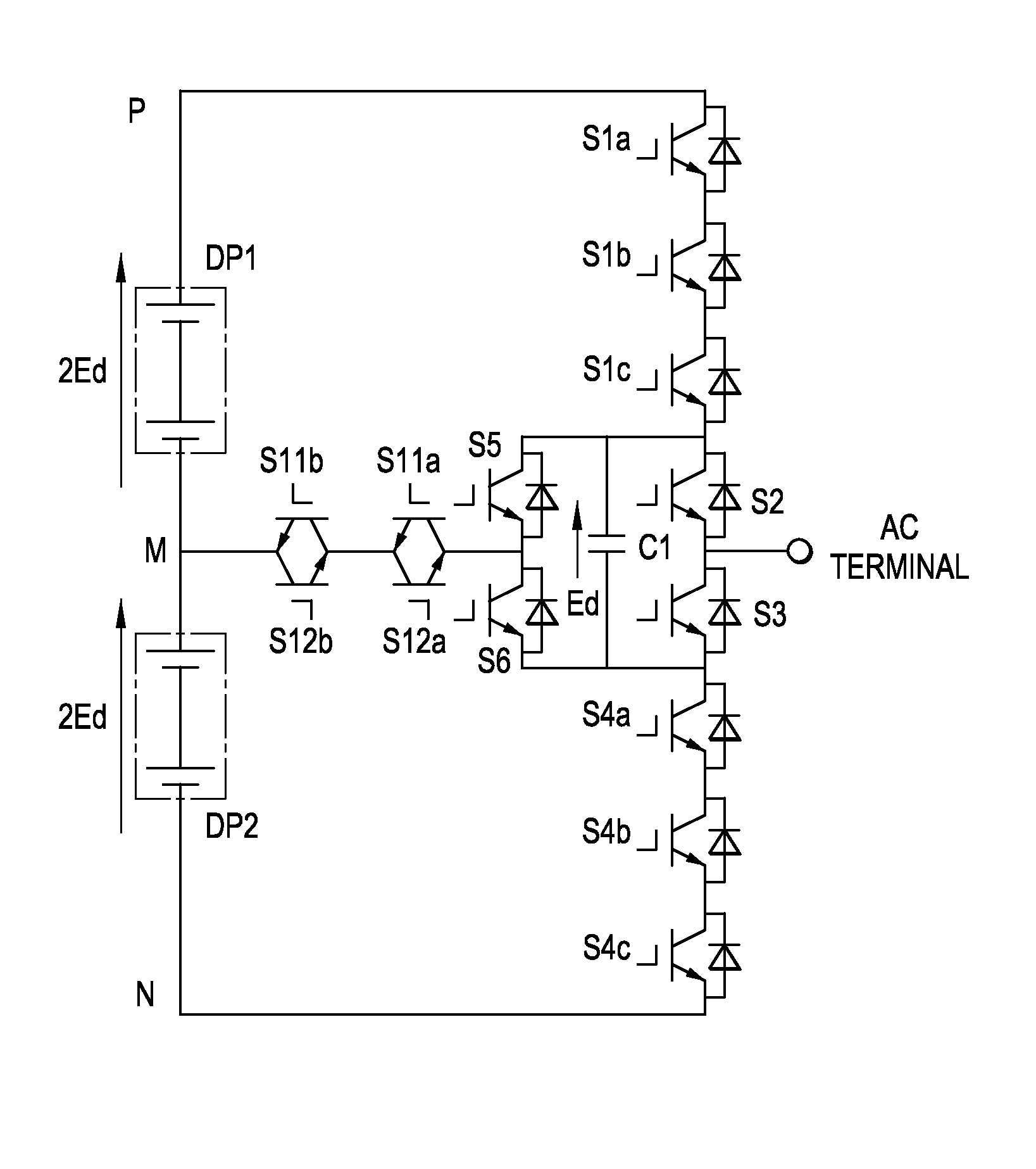
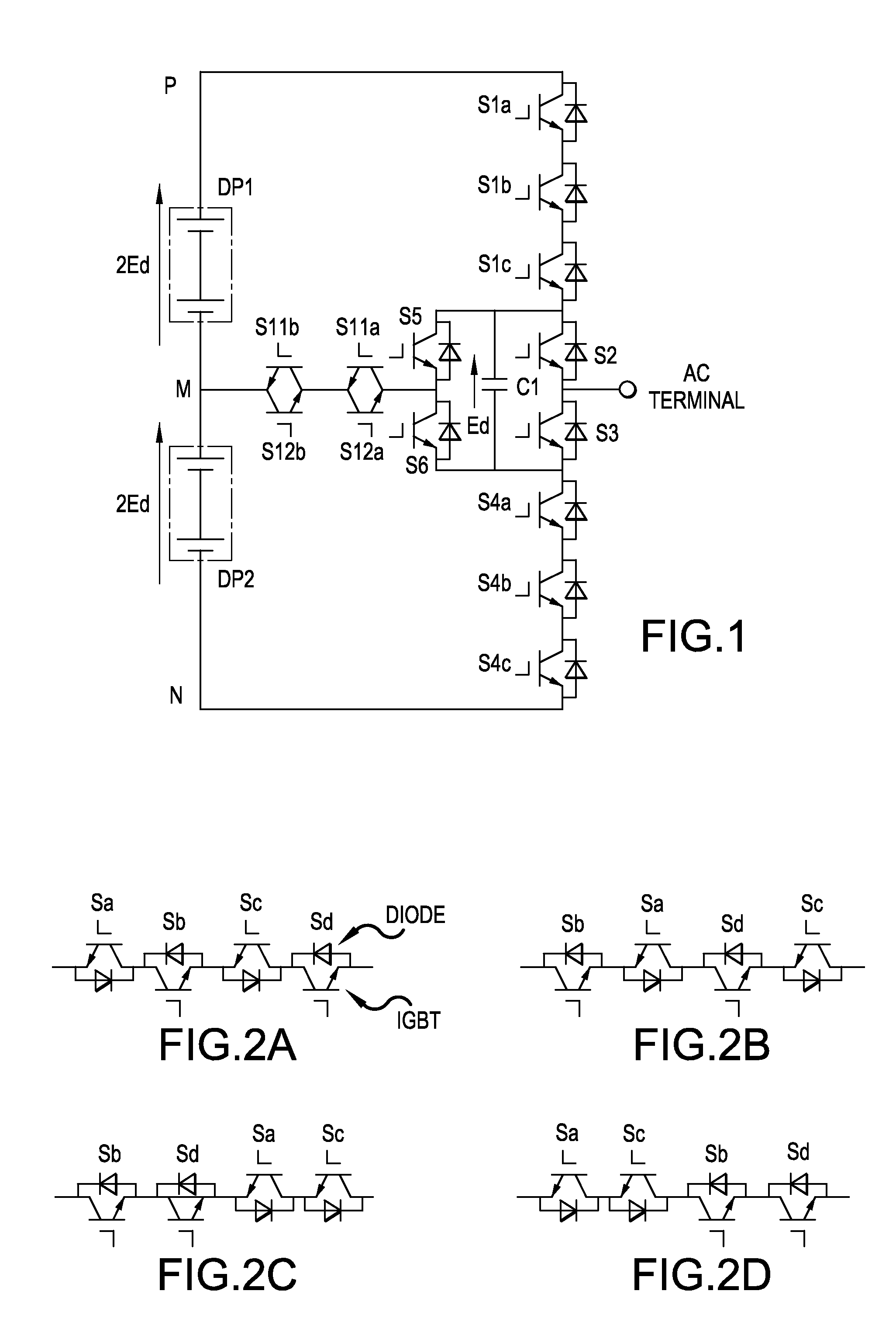
[0044]FIG. 1 shows Embodiment Example 1 of the present invention. This is a circuit construction of one phase of a five-level power conversion circuit. Two sets of this circuit composes a single phase inverter circuit, and three sets of this circuit composes a three phase inverter circuit. By connecting a load at the AC terminal, this circuit can be operated as a DC to AC power conversion circuit; by connecting an AC power supply and a reactor (inductor) at the AC terminal, the circuit can be operated as an AC to DC power conversion circuit.

[0045]The circuit of FIG. 1 comprises a DC power supply circuit composed of DC power supplies DP1 and DP2 connected in series each delivering a voltage of 2Ed. The DC power supply circuit has a positive potential terminal P, a negative potential terminal N, and a middle potential terminal M.

[0046]Eight semiconductor switches S1a, S1b, S1c, S2, S3, S4a, S4b, and S4c are connected in series between the positive potential terminal P and the negative...

embodiment example 2

[0058]FIG. 5 shows Embodiment Example 2 of the present invention. Embodiment Example 2 is an example of application to a seven-level conversion circuit shown in FIG. 15. DC power supplies DP1 and DP2 each delivering a voltage of 3Ed are connected in series. The DC power supply circuit consisting of the DC power supplies DP1 and DP2 has a positive potential terminal P, a negative potential terminal N, and a middle potential terminal M. Twelve semiconductor switches S1a through S1d, S2, S3, S4, S5, S6a through S6d are connected in series between the positive potential terminal P and the negative potential terminal N. These semiconductor switches are IGBTs each having an antiparallel-connected diode. The semiconductor switches S1a through S1d are connected in series to compose a first semiconductor switch group, and the semiconductor switches S6a through S6d are connected in series to compose a second semiconductor switch group. The semiconductor switch S2 is referred to as a first sem...


PUM


Abstract

A multilevel power conversion circuit using a flying capacitor(s) can include two bidirectional switches connected in series between a middle potential terminal of DC power supplies and a conversion circuit using semiconductor switches. Gate driving circuits for the bidirectional switches are provided with a short-circuit fault detecting circuit for detecting short-circuit of the semiconductor switching device composing the bidirectional switch circuit in an OFF signal period. Upon detection of a short-circuit fault, all semiconductor switching devices are interrupted to stop the whole system.

Description

CROSS-REFERENCE TO RELATED APPLICATION[0001]This application is based on, and claims priority to, Japanese Patent Application No. 2013-133659, filed on Jun. 26, 2013, the contents of which are incorporated herein by reference.BACKGROUND OF THE INVENTION[0002]1. Field of the Invention[0003]Embodiments of the invention relate to multilevel power conversion circuits for AC motor driving.[0004]2. Description of the Related Art[0005]FIG. 6 shows a power conversion circuit to convert a DC power to an AC power disclosed in Japanese Unexamined Patent Application Publication No. 2012-182974 and International Patent Publication Number WO / 2007 / 087732. This is an example of five-level inverter circuit. The circuit comprises DC power supplies DP1 and DP2 connected in series each supplying a voltage of 2Ed. The DC power supply circuit including the power supplies DP1 and DP2 has a positive potential terminal P, a negative potential terminal N, and a middle potential terminal M. The DC power suppl...

Claims


Application Information

Patent Timeline
Patent Type & Authority Applications(United States)
IPC IPC(8): H02M7/797
CPCH02M7/797H02M7/483H02M1/32H02M7/487H02M1/0095H02M7/4837
Inventor TAKIZAWA, SATOKI
Owner FUJI ELECTRIC CO LTD
Why Eureka
Try Eureka