
Coaxial cable and connector

a technology of coaxial cable and connector, which is applied in the direction of coupling base/case, two-part coupling device connection, coupling device connection, etc., can solve the problems of affecting the location of the connector, the inner dielectric length of the connector should be increased, and the insulation performance deteriorate, so as to achieve high efficiency

Inactive Publication Date: 2015-01-01
ELECTRONICS & TELECOMM RES INST
View PDF3 Cites 4 Cited by
  • Summary
  • Abstract
  • Description
  • Claims
  • Application Information

AI Technical Summary

Benefits of technology

The present invention aims to solve the problems in the conventional art by providing a coaxial cable and connector that can meet both high-voltage insulation and high frequency ultra-wideband impedance matching requirements, allowing for efficient transmission of high-frequency high-power signals.

Problems solved by technology

To provide a configuration that is compatible with the connector inner electrode and the cable dielectric 3 increased in the lengthwise direction, problems arise in that the length of the inner dielectric of the connector should be increased accordingly, insulation performance is deteriorated by the bending characteristic of the cable due to high-voltage characteristics, and a spatial limitation is imposed on wiring and the location of the connector.
Accordingly, this conventional technology is problematic in that signal transfer efficiency is deteriorated in GHz or higher high-frequency bands.
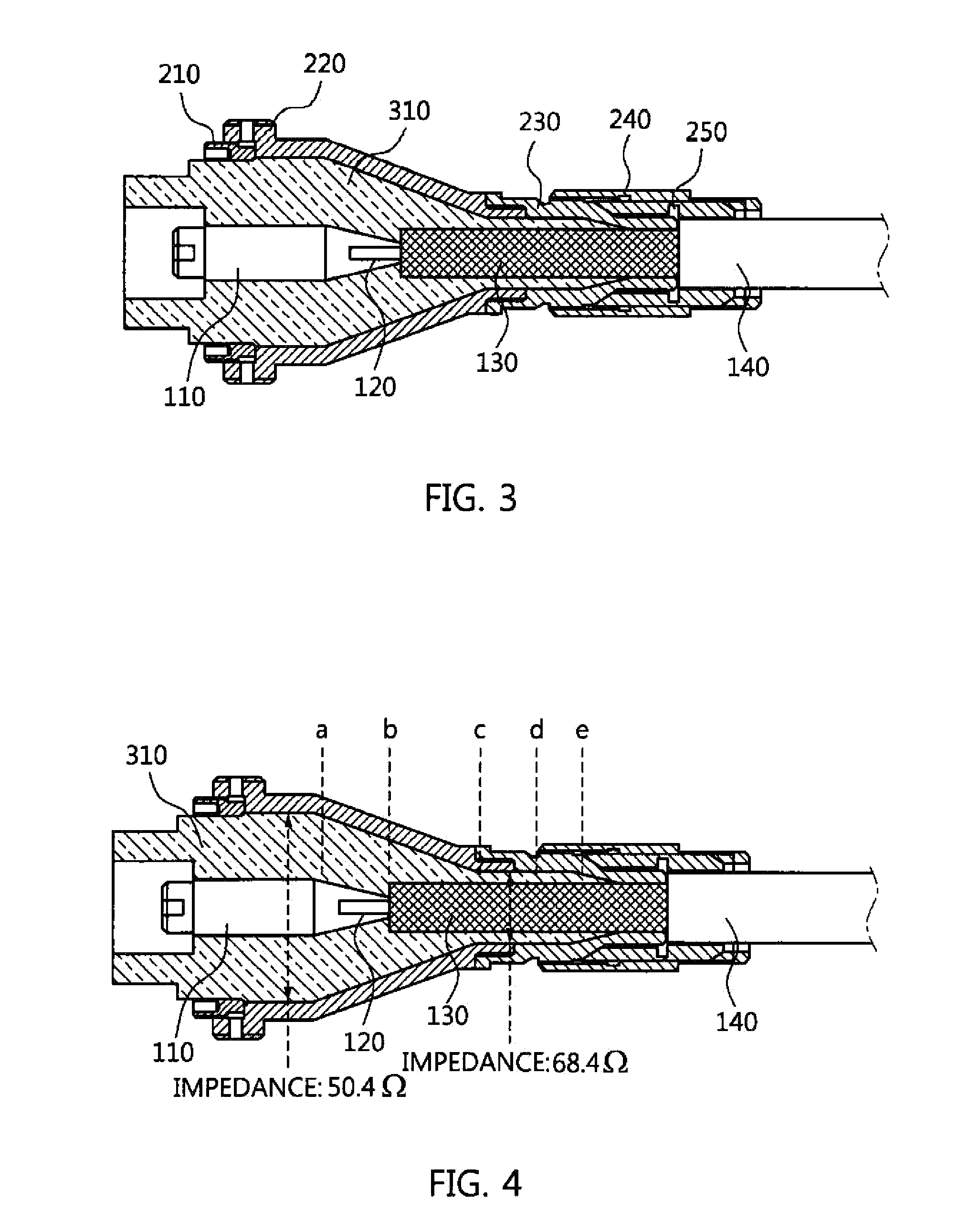
As a result, the conventional technology of FIGS. 3 to 5 has impedance matching performance that is sufficient to transfer several ten kV or higher and several nanosecond or shorter signals and that is insufficient to transfer several ten kV or high and sub-nanosecond or GHz or higher high-voltage high frequency ultra-wideband signals with high efficiency using a 50 ohm system.

Method used


Image

  • Coaxial cable and connector
  • Coaxial cable and connector
  • Coaxial cable and connector

Examples


Embodiment Construction

[0041]A coaxial cable and connector according to the present invention will be described with reference to the accompanying drawings. Prior to the following detailed description of the present invention, it should be noted that the terms and words used in the specification and the claims should not be construed as being limited to ordinary meanings or dictionary definitions. Meanwhile, the embodiments described in the specification and the configurations illustrated in the drawings are merely examples and do not exhaustively present the technical spirit of the present invention. Accordingly, it should be appreciated that there may be various equivalents and modifications that can replace the examples at the time at which the present application is filed.

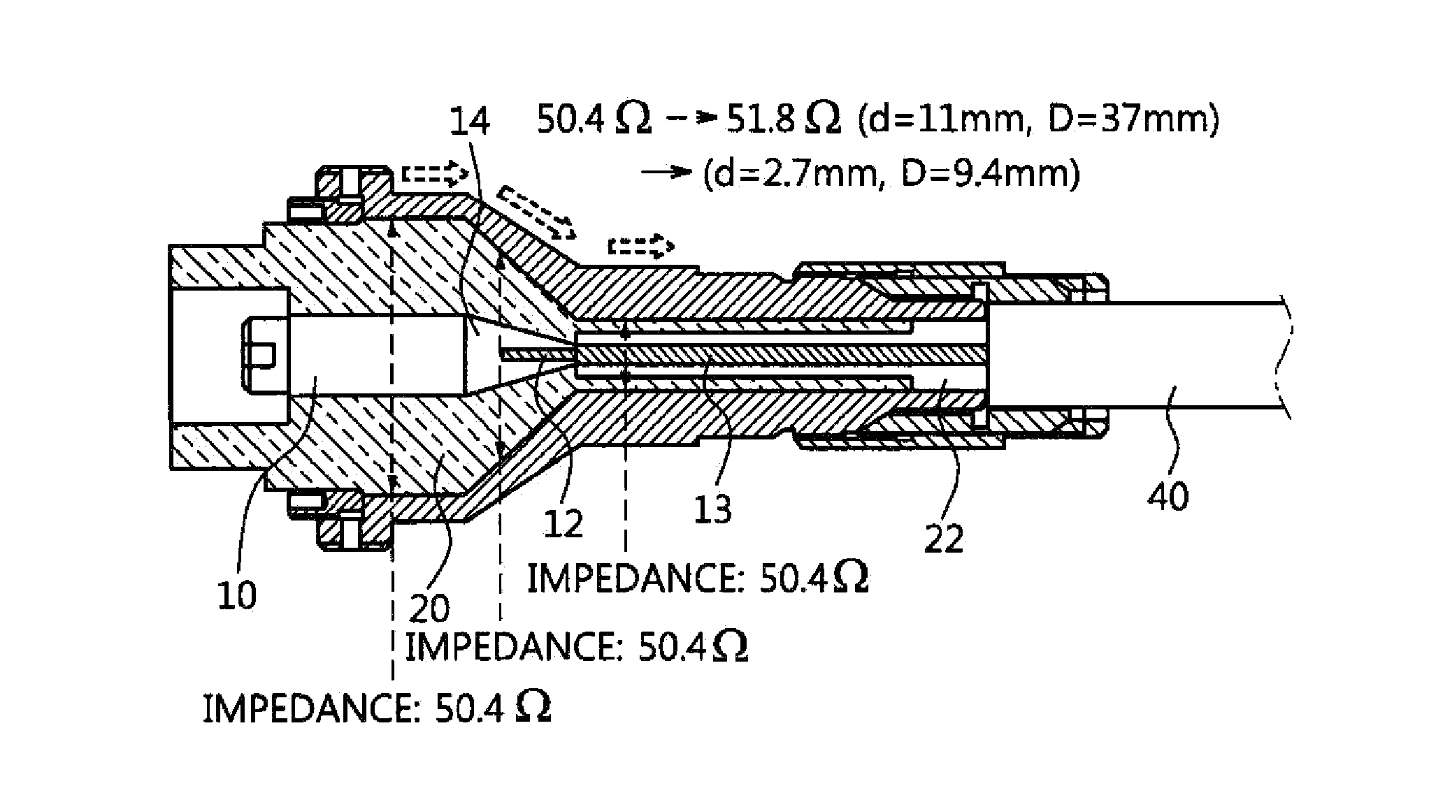
[0042]FIG. 6 is a diagram illustrating the structure of a coaxial cable and a connector according to an embodiment of the present invention.

[0043]Referring to FIG. 6, the coaxial cable is connected to one side of the connector, and i...


PUM


Abstract

The coaxial cable includes a central conductor, a cable dielectric formed along the outer circumferential surface of the central conductor, and a protruding central conductor configured to protrude from one side of the central conductor and be exposed from the cable dielectric. The diameter of the central conductor is equal to the outer diameter of an end of a transition electrode formed on one side of a connector inner electrode. The connector includes a connector inner electrode configured to be selectively coupled to and separated from a coaxial cable having a central conductor, and provided with a transition electrode on one side thereof, and a connector dielectric formed along the outer circumferential surface of the connector inner electrode. The outer diameter of an end of the transition electrode is equal to the diameter of the central conductor of the coaxial cable.

Description

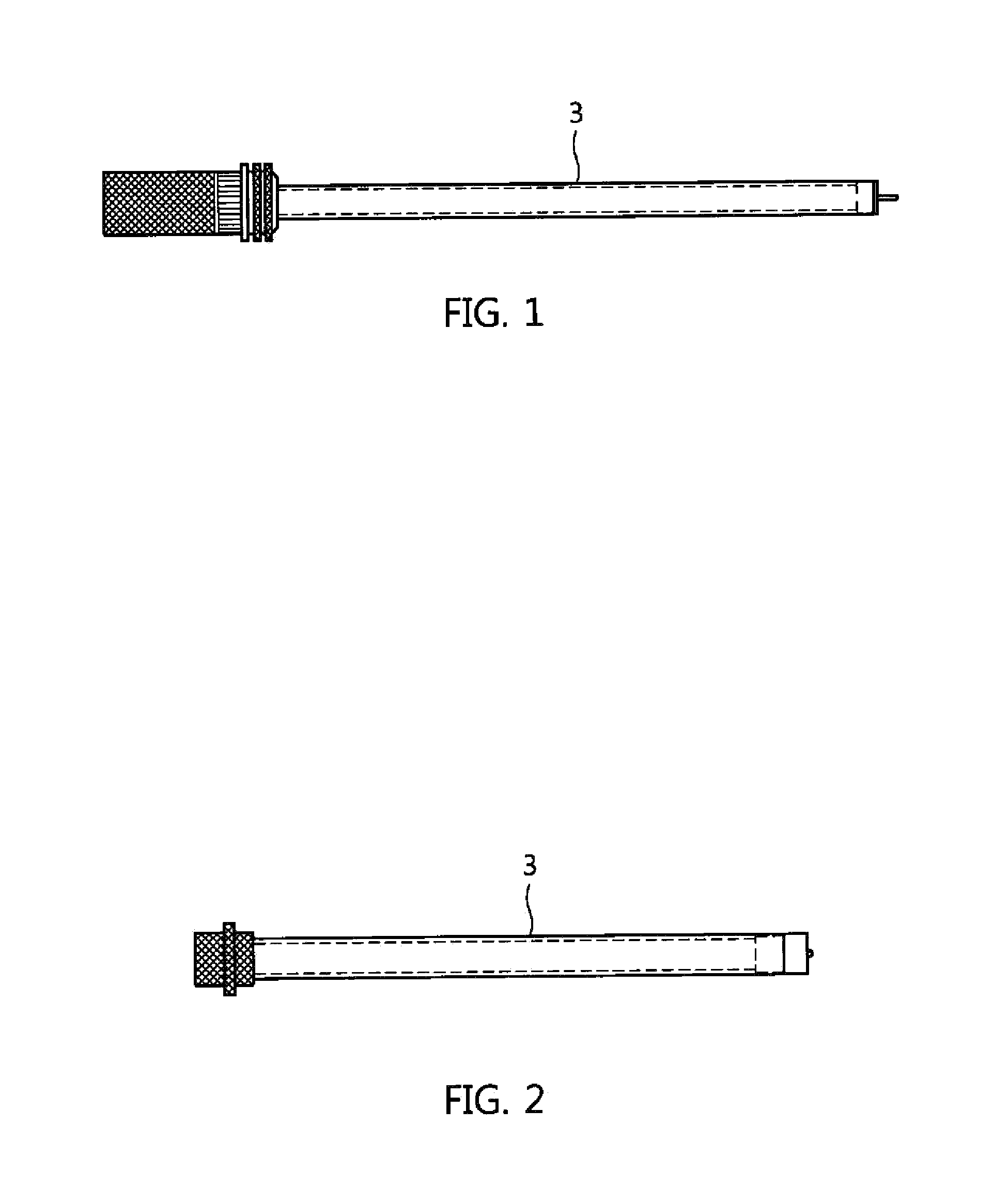
CROSS REFERENCE TO RELATED APPLICATION[0001]This application claims the benefit of Korean Patent Application No. 10-2013-0074670, filed on Jun. 27, 2013, which is hereby incorporated by reference in its entirety into this application.BACKGROUND OF THE INVENTION[0002]1. Technical Field[0003]The present invention relates generally to a coaxial cable and a connector and, more particularly, to a coaxial cable and a connector that are capable of transmitting impulse signals and continuous sine wave signals having high-voltage, high-power, ultra-wideband characteristics.[0004]2. Description of the Related Art[0005]A high-voltage coaxial cable is formed by surrounding an internal core wire formed of a conductor with an insulation and impedance matching dielectric and then covering the dielectric with an additional conductor, and is used to transmit high-voltage pulse signals without causing dielectric breakdown.[0006]FIGS. 1 and 2 are diagrams illustrating general high-voltage connector he...

Claims


Application Information

Patent Timeline
Patent Type & Authority Applications(United States)
IPC IPC(8): H01R9/05
CPCH01R9/0503H01R24/44H01R13/53H01B11/18
Inventor RYU, SEUNG-KABLEE, KYUNG-HOONCHU, KWANG-UK
Owner ELECTRONICS & TELECOMM RES INST
Learn More