Image Analysis Apparatus, Method, and Program

a technology of image analysis and apparatus, applied in the field of image analysis apparatus, method and program, can solve the problem of not being able to confirm the ventilation volume of the lungs, and achieve the effect of more accurate quantification of the differen

Active Publication Date: 2015-01-01
FUJIFILM CORP
View PDF3 Cites 26 Cited by
  • Summary
  • Abstract
  • Description
  • Claims
  • Application Information

AI Technical Summary

Benefits of technology

[0037]Further, the quantification of a difference between the local ventilation volume function and the benchmark ventilation volume function after normalizing the functions in a time ax

Problems solved by technology

The method described in U.S. Patent Application Publication No. 20080009683 may check the three-dimensional lung

Method used


Image

  • Image Analysis Apparatus, Method, and Program
  • Image Analysis Apparatus, Method, and Program
  • Image Analysis Apparatus, Method, and Program

Examples


Embodiment Construction

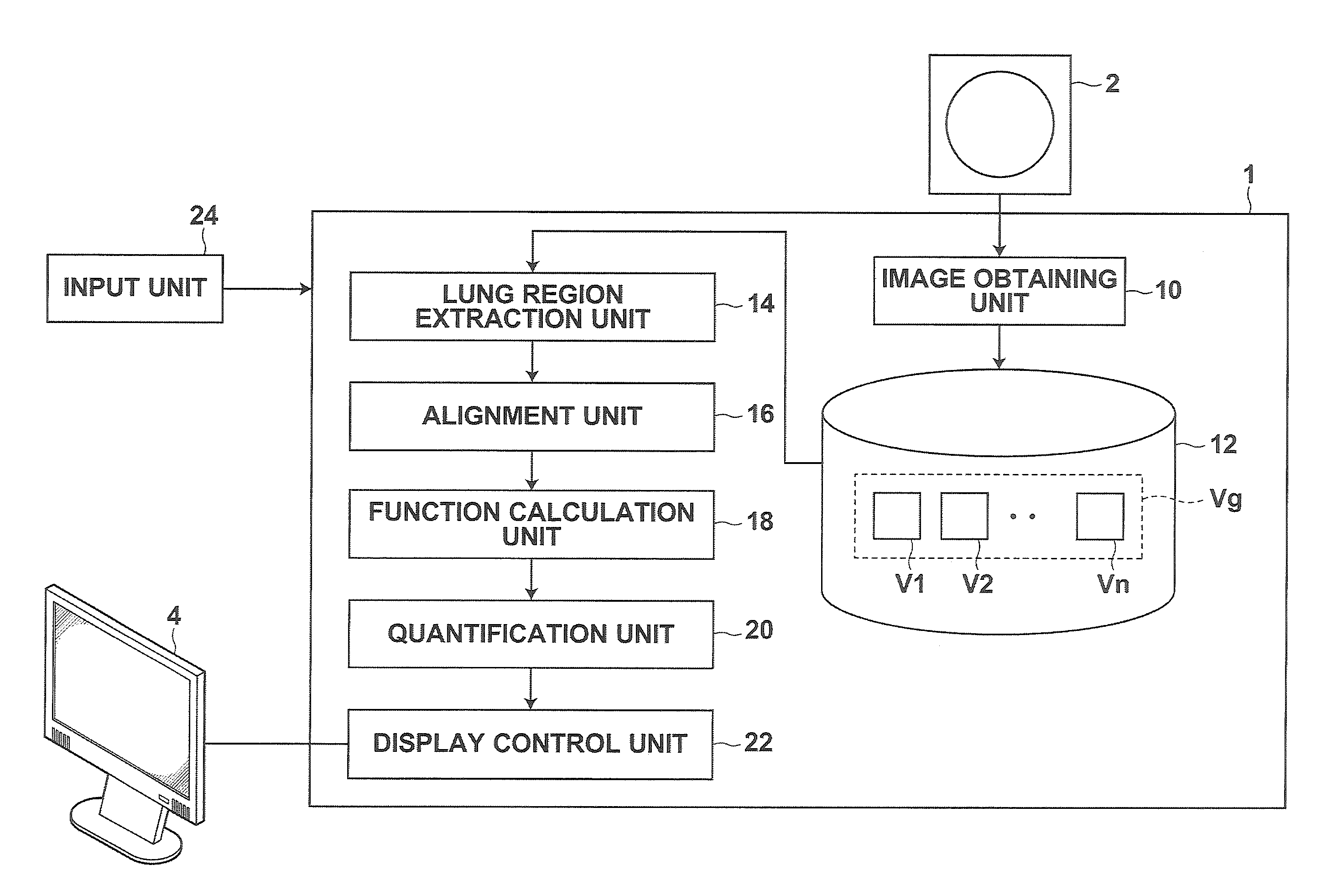
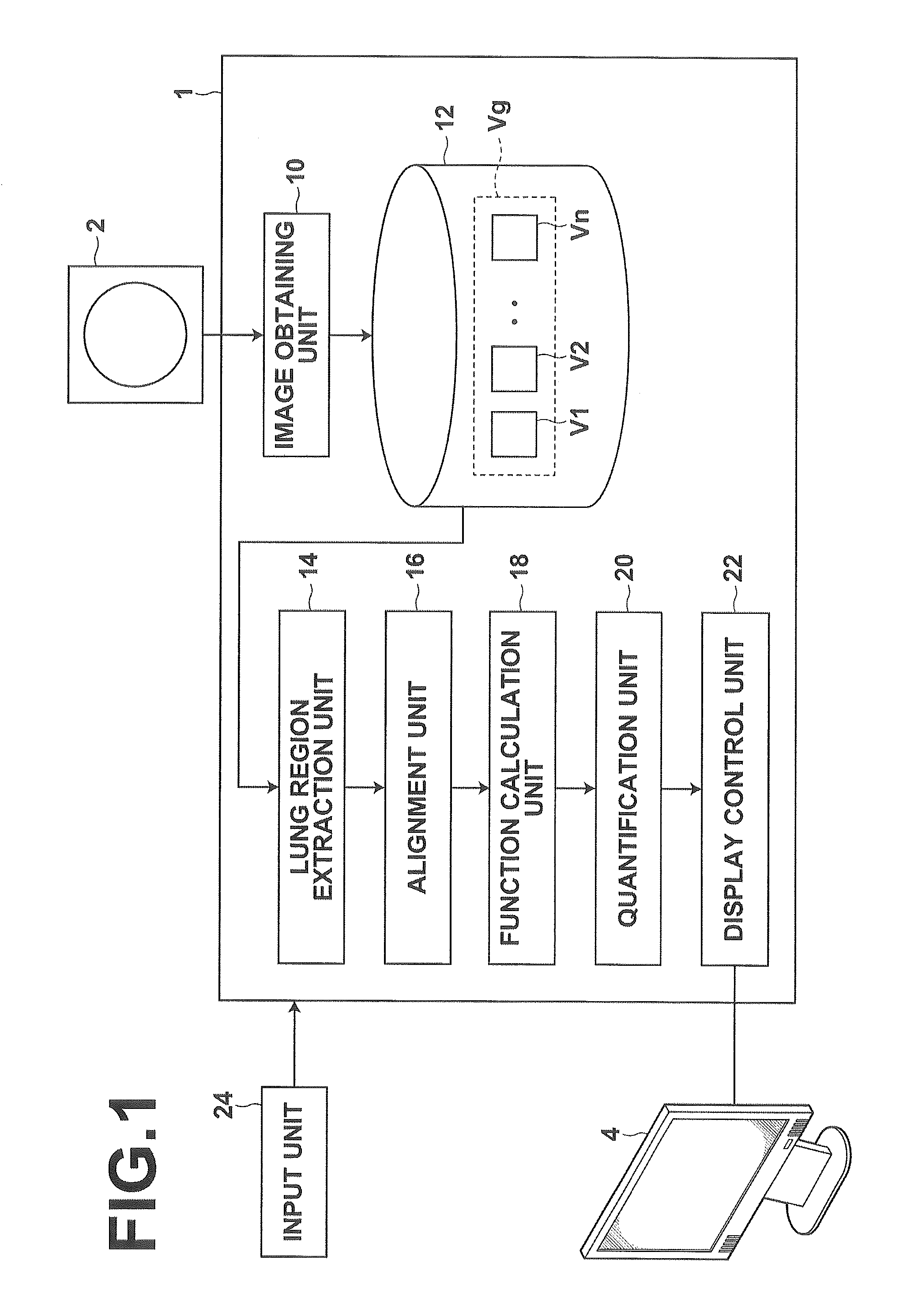
[0049]Hereinafter, embodiments of the present invention will be described with reference to the accompanying drawings. FIG. 1 is a schematic block diagram of an image analysis apparatus according to an embodiment of the present invention, illustrating a configuration thereof. The configuration of the image analysis apparatus 1 shown in FIG. 1 is realized by executing an image analysis program read into an auxiliary storage unit on a computer.

[0050]The image analysis program is provided being recorded on a storage medium, such as CD-ROM and the like, or distributed via a network, such as the Internet, and installed on a computer.

[0051]The image analysis apparatus 1 according to the present embodiment includes an image obtaining unit 10, a storage unit 12, a lung region extraction unit 14, an alignment unit 16, a function calculation unit 18, a quantification unit 20, a display control unit 22, and input unit 24.

[0052]The image obtaining unit 10 has a communication interface function ...


PUM


Abstract

The region extraction unit extracts lung regions from three-dimensional images of a plurality of time phases, the alignment unit aligns pixel position in the lung region extracted from each three-dimensional image between the three-dimensional images. This calculates a displacement vector field at each time phase of the three-dimensional images. The function generation unit calculates a local ventilation volume function representing a temporal change in ventilation volume at each point in the displacement vector field, and the quantification unit calculates a difference function, which is a function of difference values between the local ventilation volume function and benchmark ventilation volume function, as a quantitative value representing a difference between the local ventilation volume function and the benchmark ventilation volume function. The display control unit displays lung VR images on which the difference function is mapped on the display in time series order.

Description

CROSS-REFERENCE TO RELATED APPLICATIONS[0001]This application is a Continuation of PCT International Application No. PCT / JP2013 / 001640 filed on Mar. 13, 2013, which claims priority under 35 U.S.C. §119 (a) to Japanese Patent Application No. 2012-066598 filed on Mar. 23, 2012. Each of the applications is hereby expressly incorporated by reference, in its entirety, into the present application.BACKGROUND OF THE INVENTION[0002]1. Technical Field[0003]The present invention relates to an image analysis apparatus and method for analyzing a three-dimensional distribution of ventilation volume of lungs using three-dimensional images representing motion of the lungs during respiration, and a program for causing a computer to perform the image analysis method.BACKGROUND ART[0004]Recently, high quality three-dimensional images are used in image diagnosis with the advancement of medical equipment (e.g., multi-detector CT, hereinafter referred to as multi-slice CT, and the like). In the multi-sl...

Claims


Application Information

Patent Timeline
IPC IPC(8): G06T7/00A61B5/091G06T7/20A61B5/055A61B6/03
CPCG06T7/20A61B5/091A61B5/055G06T2207/30061G06T7/0028G06T2207/10084G06T2207/10088A61B6/032A61B5/113A61B6/037A61B6/461A61B6/50A61B6/5217G06T7/0016G06T7/602G06T2207/10072G06T2207/10081G06T7/33G06T7/62G16H50/30
Inventor MASUMOTO, JUN
Owner FUJIFILM CORP
Why Eureka
Try Eureka