
Composite of III-Nitride Crystal on Laterally Stacked Substrates

a technology of iii-nitride crystal and substrate, which is applied in the direction of crystal growth process, polycrystalline material growth, chemically reactive gas, etc., can solve the problems of /sub>n crystal of superior crystallinity that has not been obtainable, and achieves superior crystallinity and light-emission efficiency. , the effect of superior crystallinity

Active Publication Date: 2015-01-08
SUMITOMO ELECTRIC IND LTD
View PDF35 Cites 6 Cited by
  • Summary
  • Abstract
  • Description
  • Claims
  • Application Information

AI Technical Summary

Benefits of technology

The present invention provides an epitaxial III-nitride crystal with superior crystal quality and specific properties. This crystal can be used to create semiconductor devices with efficient light-emission. The "technical effect" is the production of high-quality epitaxial III-nitride crystals with superior properties, which can be utilized in the manufacturing of semiconductor devices.

Problems solved by technology

With the method in Pat. App. Pub. No. 2005-162526, however, inasmuch as growth of the GaN crystal is carried out with, as seeds, the masses of crystal GaN that have been embedded into the sapphire substrate, due to the disparity in thermal expansion coefficient between sapphire and GaN, fractures and strains appear in the GaN crystal when the crystal is cooled following the growth process, such that GaN crystal of superior crystallinity has not been obtainable.
Furthermore, if III-nitride crystal containing Al—for example, AlxGayIn1-x-yN (x>0, y≧0, x+y≧1)—is grown by the method in Pat. App. Pub. No. 2005-162526, because the Al precursor is not selective with respect to the silicon oxide film, the AlxGayIn1-x-yN grows onto the silicon oxide film as well, and consequently AlxGayIn1-x-yN crystal of superior crystallinity has not been obtainable.

Method used


Image

  • Composite of III-Nitride Crystal on Laterally Stacked Substrates
  • Composite of III-Nitride Crystal on Laterally Stacked Substrates
  • Composite of III-Nitride Crystal on Laterally Stacked Substrates

Examples


embodiment 1

[0098]To begin with, referring to FIG. 3A, the (0001) face and (000-1) face—the two major surfaces—of GaN bulk crystal (III-nitride bulk crystal 1) were ground and polished to bring the roughness average Ra of either major surface to 5 nm. Here measurement of the surface roughness average Ra was carried out by AFM.

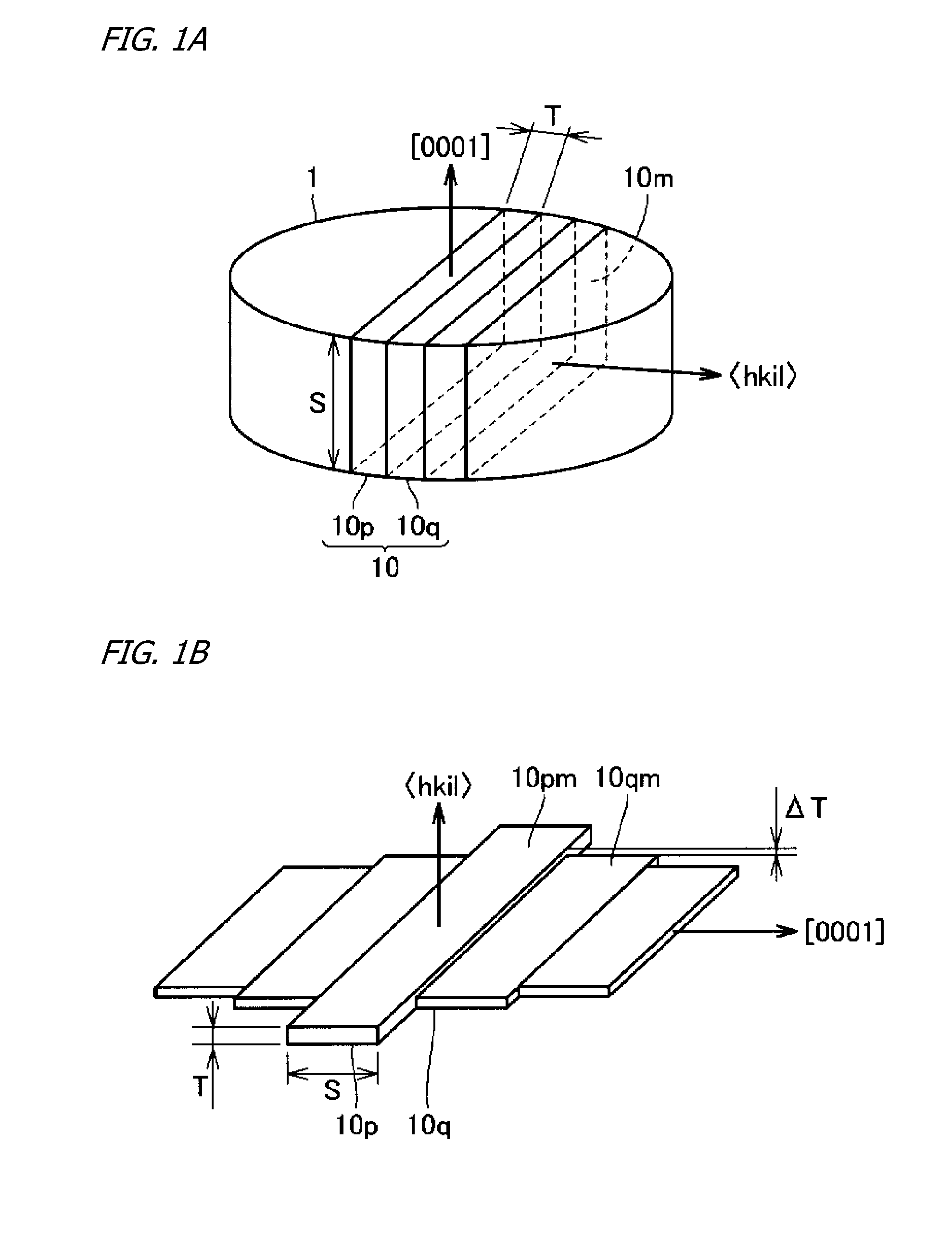
[0099]Next, referring to FIG. 3A, the GaN bulk crystal (III-nitride bulk crystal 1) whose roughness average Ra on either of its major surfaces had been made 5 nm was sawed along a plurality of planes perpendicular to a direction to slice off a plurality of GaN crystal substrates (III-nitride crystal substrates 10p, 10q) whose width S was 3 mm, length L was 20 to 50 mm, and thickness T was 1 mm, having {1-100} major surfaces. Subsequently, the not-ground and not-polished four sides of each sliced-off GaN crystal substrate were ground and polished, to bring the roughness average Ra of the four surfaces to 5 nm. A plurality of GaN crystal substrates whose roughness average R...

embodiment 2

[0106]Reference is again made to FIG. 3A: Apart from grinding and polishing the (0001) face and (000-1) face—the two major surfaces—of GaN bulk crystal (III-nitride bulk crystal 1) to bring the roughness average Ra of either major surface to 50 nm, in the same manner as in Embodiment 1, plural GaN crystal substrates (III-nitride crystal substrates 10p, 10q) were sliced off, and the not-ground and not-polished four sides of each GaN crystal substrate were ground and polished, to bring the roughness average Ra of the four surfaces to 5 nm. Among the plurality of GaN crystal substrates were GaN crystal substrates whose major-surface plane orientation did not coincide perfectly with {1-100}, but the plane orientation of the major surface of such GaN crystal substrates in all cases was misoriented by 5° or less with respect to {1-100}.

[0107]Next, referring to FIG. 3B, the plural GaN crystal substrates (III-nitride crystal substrates10p, 10q) were situated in the same manner as in Embodim...

embodiment 3

[0112]To begin with, referring to FIG. 5A, the (0001) face and (000-1) face—the two major surfaces—of GaN bulk crystal (III-nitride bulk crystal 1) were ground and polished to bring the roughness average Ra of either major surface to 5 nm.

[0113]Next, again referring to FIG. 5A: The GaN bulk crystal (III-nitride bulk crystal 1) whose roughness average Ra on either of its major surfaces had been made 5 nm was sawed along a plurality of planes perpendicular to a direction to slice off a plurality of GaN crystal substrates (III-nitride crystal substrates 10p, 10q) whose width S was 3 mm, length L was 20 to 50 mm, and thickness T was 1 mm, having {11-20} major surfaces. Subsequently, the not-ground and not-polished four sides of each sliced-off GaN crystal substrate were ground and polished, to bring the roughness average Ra of the four surfaces to 5 nm. A plurality of GaN crystal substrates whose roughness average Ra on the {11-20} major surfaces was 5 nm was thus obtained. Among these...


PUM

PropertyMeasurementUnit
widthaaaaaaaaaa
full-width-at-half-maximumsaaaaaaaaaa
heightaaaaaaaaaa

Abstract

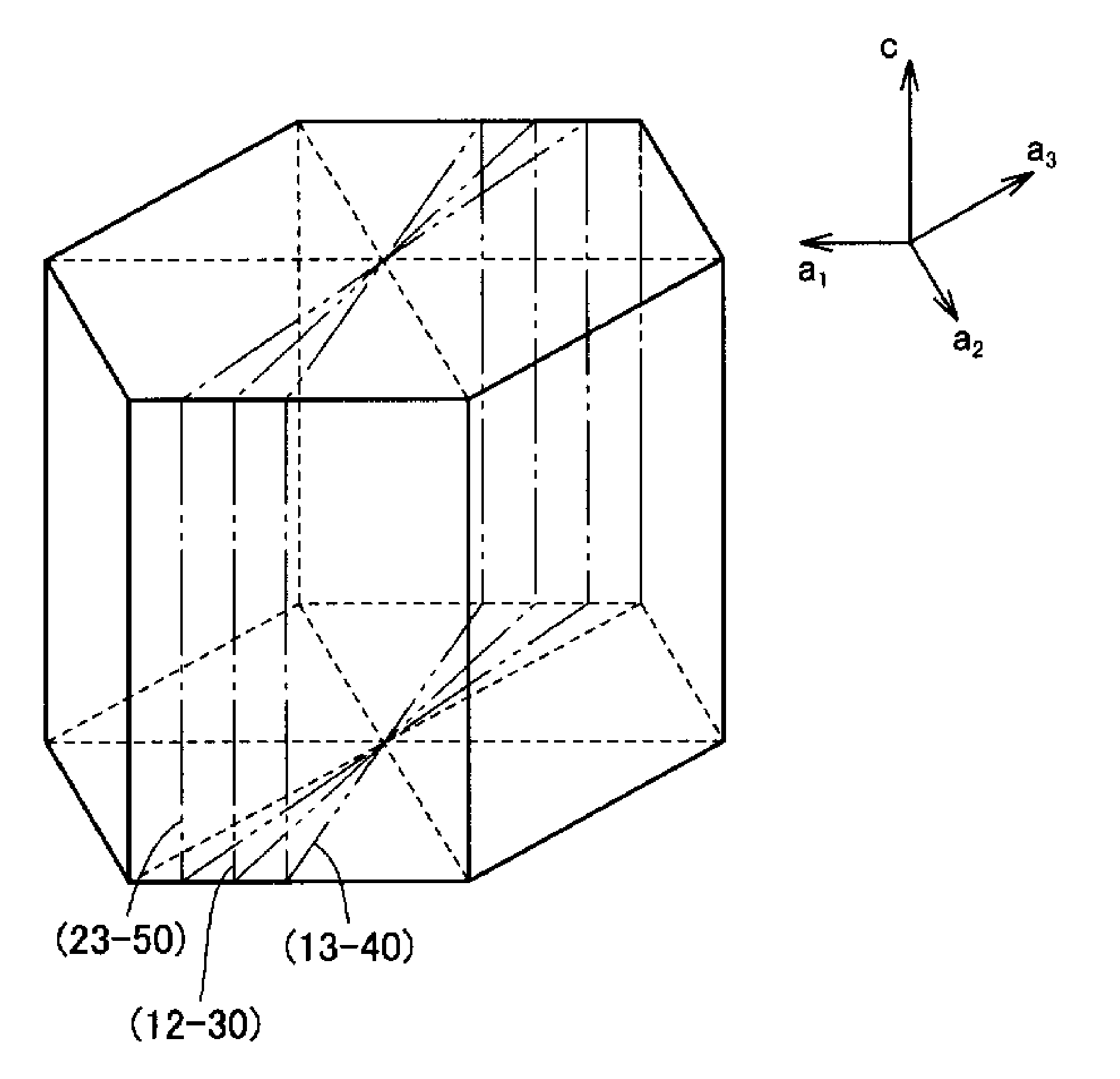
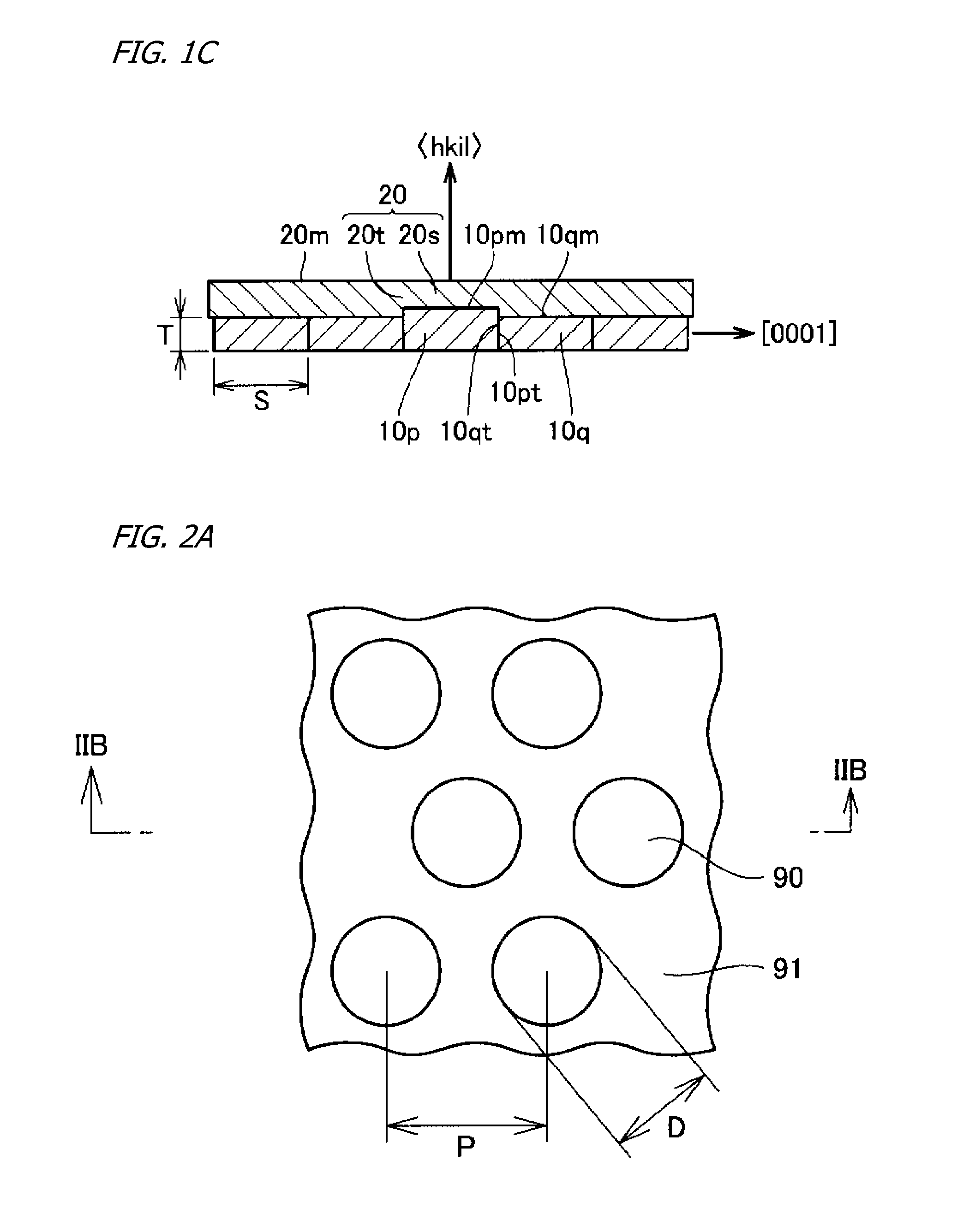
Group-III nitride crystal composites made up of especially processed crystal slices, cut from III-nitride bulk crystal, whose major surfaces are of {1-10±2}, {11-2±2}, {20-2±1} or {22-4±1} orientation, disposed adjoining each other sideways with the major-surface side of each slice facing up, and III-nitride crystal epitaxially present on the major surfaces of the adjoining slices, with the III-nitride crystal containing, as principal impurities, either silicon atoms or oxygen atoms. With x-ray diffraction FWHMs being measured along an axis defined by a <0001> direction of the substrate projected onto either of the major surfaces, FWHM peak regions are present at intervals of 3 to 5 mm width. Also, with threading dislocation density being measured along a <0001> direction of the III-nitride crystal substrate, threading-dislocation-density peak regions are present at the 3 to 5 mm intervals.

Description

CROSS-REFERENCE TO RELATED APPLICATIONS[0001]This is a continuation-in-part of application Ser. No. 14 / 194,830, filed on Mar. 3, 2014. Application Ser. No. 14 / 194,830 was a continuation of application Ser. No. 13 / 762,401, filed on Feb. 8, 2013, and now U.S. Pat. No. 8,709,923. Application Ser. No. 13 / 762,401 was a continuation of Ser. No. 13 / 564,731, filed on Aug. 2, 2012 and now U.S. Pat. No. 8,404,042. Application Ser. No. 13 / 564,731 was a continuation-in-part of application Ser. No. 12 / 467,297 filed on May 17, 2009 and now U.S. Pat. No. 8,258,051. Application Ser. No. 12 / 467,297 was a continuation-in-part of International Application No. PCT / JP2007 / 072096, filed on Nov. 14, 2007.BACKGROUND OF THE INVENTION[0002]1. Technical Field[0003]The present invention, involving Group-III nitride crystal manufacturing methods, relates to epitaxial III-nitride crystal in composites in which the epitaxial crystal has a major surface of plane orientation other than {0001}, designated by choice,...

Claims


Application Information

Patent Timeline
Patent Type & Authority Applications(United States)
IPC IPC(8): H01L29/04H01L29/20
CPCH01L29/2003H01L29/045C30B9/12C30B19/02C30B23/025C30B25/20C30B29/403C30B29/406H01L21/02389H01L21/02433H01L21/0254H01L21/02658H01L29/73H01L29/772H01L29/778H01L29/872H01L33/16C30B25/18
Inventor MIZUHARA, NAHOUEMATSU, KOJIMIYANAGA, MICHIMASATANIZAKI, KEISUKENAKAHATA, HIDEAKINAKAHATA, SEIJIOKAHISA, TAKUJI
Owner SUMITOMO ELECTRIC IND LTD
Learn More