Heat-exchange apparatus for insertion into a storage tank, and mounting components therefor

a technology of heat exchange apparatus and storage tank, which is applied in the direction of tubular elements, heat storage plants, stationary tubular conduit assemblies, etc., can solve the problems of accelerating wear and deterioration of pump components, affecting the smooth and safe operation of hydraulic-controlled attachments, and preventing engine start-up, etc., to achieve the effect of increasing the heat-radiating surface area

Inactive Publication Date: 2015-01-15
ARNOT ROGER
View PDF7 Cites 19 Cited by
  • Summary
  • Abstract
  • Description
  • Claims
  • Application Information

AI Technical Summary

Benefits of technology

[0007]Some embodiments of the present invention relate to mounting components cooperable with the heat-exchange apparatus to sealingly engage the heat-exchange apparatus with a storage tank suitable for storing fluids, whereby a proximal section of the heat-exchange apparatus is sealingly engaged with the outer and inner walls of the storage tank and a distal section of the heat-exchange apparatus extends into the interior of the storage tank. An outer portion of the proximal section of the heat-exchange apparatus is cooperable with a first mounting component that is substantially flush with the outer wall of the storage tank. A second mounting component that is substantially flush with the inner wall of the storage tank is cooperable with the first mounting component. The first and second mounting components are releasably interconnected by fixtures that sealingly fix the proximal portion of the heat-exchange apparatus to the inner and outer walls of the storage tank. The mounting components are also useful for sealingly engaging other devices and/or instruments with storage tanks and the like.
[0008]In accordance with

Problems solved by technology

In addition, cold conditions impede the transmission of thickened diesel fuel oils from their storage tanks to engines thereby interfering with and/or preventing engine starting.
Smooth and safe operation of hydraulic-controlled attachments can also be adversely affected by cold-thickened hydraulic oil through reduced and impaired flow rates in response to manipulation of the hydraulic controls.
Additionally, cold-thickened hydraulic oil imposes significant mechanical stresses on hydraulic pumps often resulting in accelerated wearing and deterioration of the pumps' components and periodically, in pump failure.
Transfer and transmission of such stored petroleum products can be significantly debilitated as their viscosities increase as a consequenc

Method used


Image

  • Heat-exchange apparatus for insertion into a storage tank, and mounting components therefor
  • Heat-exchange apparatus for insertion into a storage tank, and mounting components therefor
  • Heat-exchange apparatus for insertion into a storage tank, and mounting components therefor

Examples


Embodiment Construction

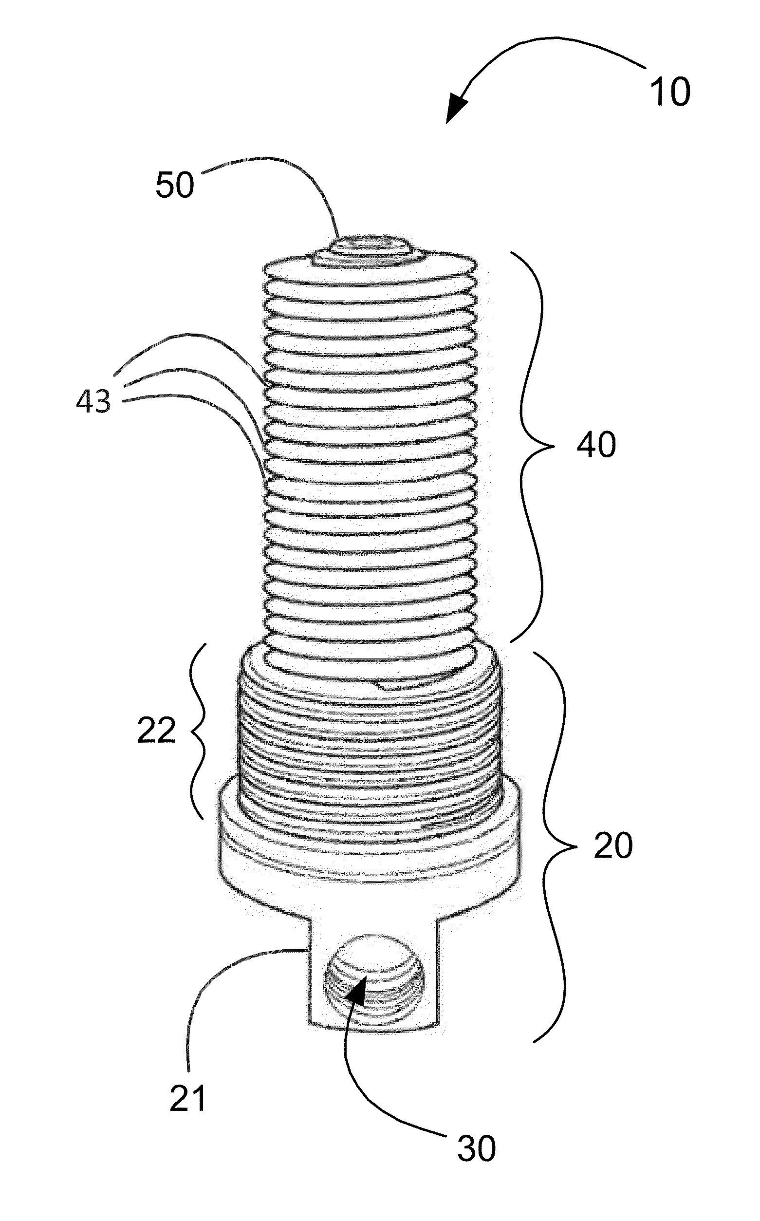
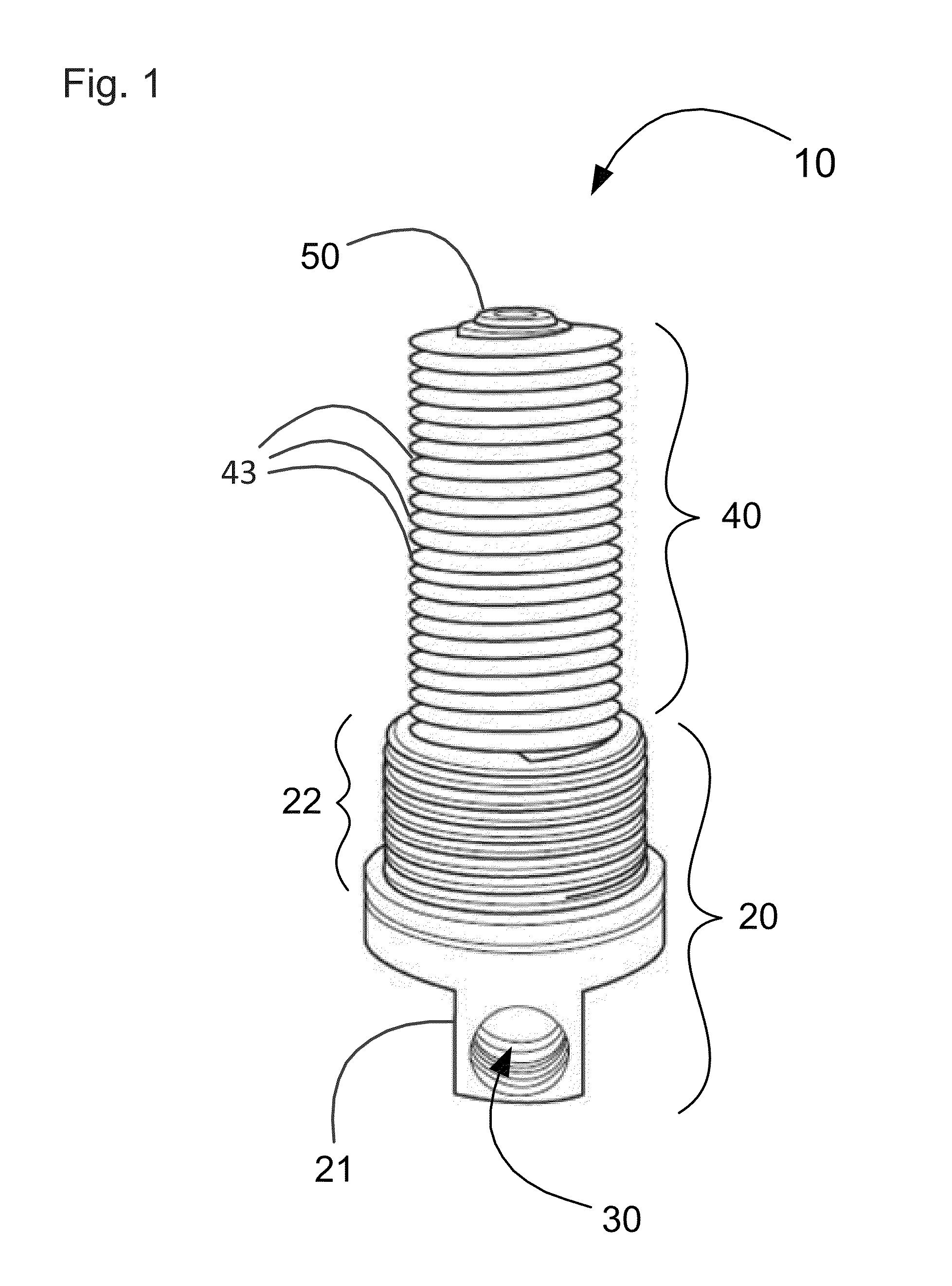
[0027]Exemplary embodiments of the present invention relate to a heat-exchange apparatus and to mounting components for sealingly engaging the heat-exchange apparatus with a storage tank wherein fluids may be stored.

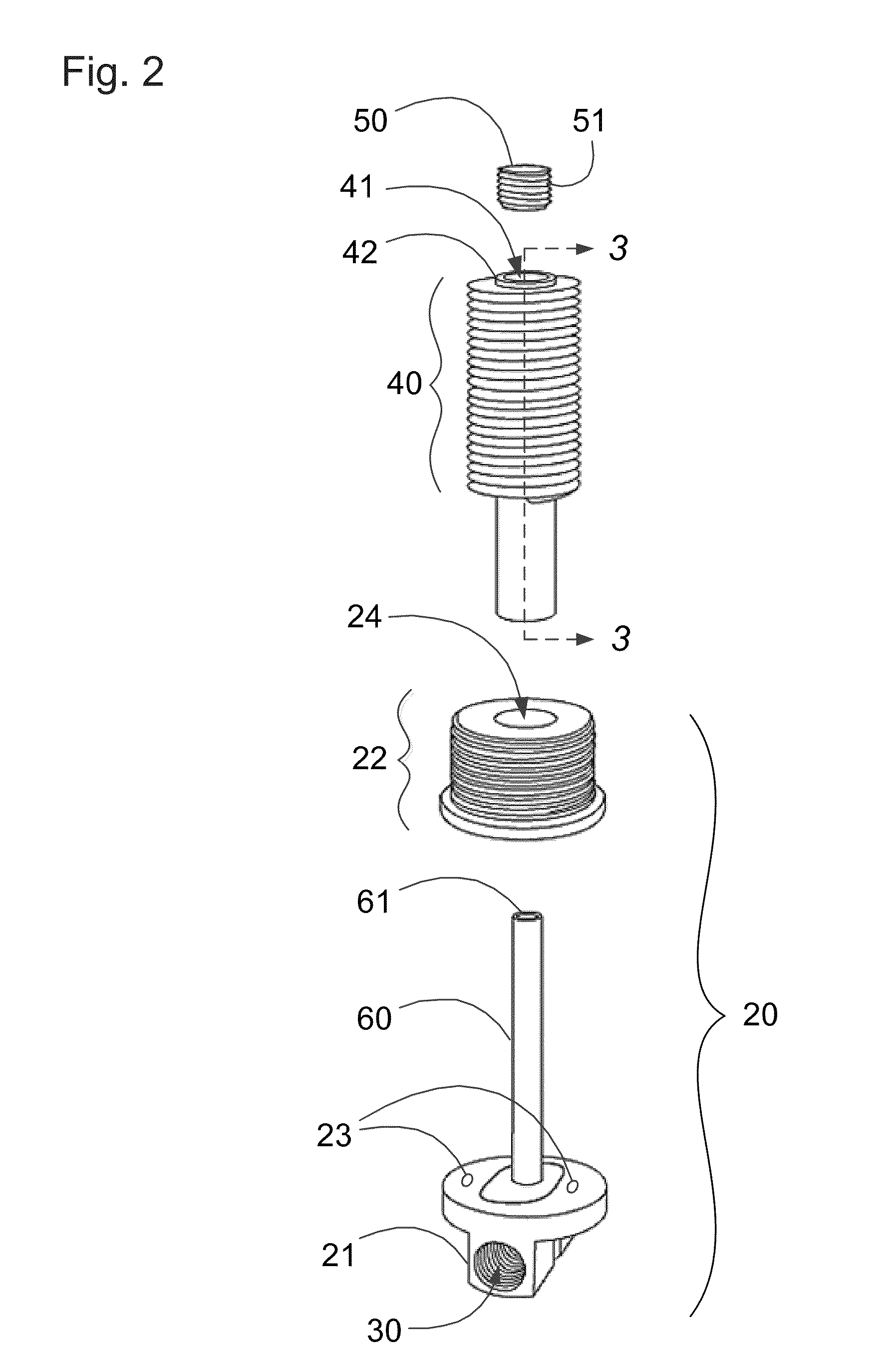
[0028]An embodiment of the present invention relates to a heat-exchange apparatus comprising a heat-exchanging component, a coupling manifold interconnectable to a fluid supply and configured to engage with the heat-exchanging component, and a hollow, elongate, flow-directing element that delivers fluid to the heat-exchanging component.

[0029]The heat-exchanging component preferably comprises a void into which the flow-directing element delivers fluid. The void may be of any suitable size provided the flow-directing element can fit therein. Preferably the void is at least about 2 mm, more preferably at least about 5 mm, in diameter. Preferably the void is less than about 100 mm, more preferably less than about 50 mm, in diameter.

[0030]In a preferred embodiment the heat-ex...


PUM

PropertyMeasurementUnit
Flow rateaaaaaaaaaa

Abstract

A heat-exchange apparatus and a mounting component set for installation into storage tanks. The heat-exchange apparatus comprises a heat-exchanging component, a coupling manifold configured to engage with the heat-exchanging component, and a hollow, elongate, flow-directing element that delivers fluid to the heat-exchanging component. The mounting component set comprises an inner flange for engaging the inner wall of the storage tank, an outer flange for engaging the outer wall of the storage tank, and at least one gasket cooperable with one of the flanges. The heat-exchange apparatus sealably engages the outer flange such that the heat-exchanging component extends into the interior of the tank, and the coupling manifold is interconnectable to an external supply of heat-exchange fluid.

Description

CROSS-REFERENCE TO RELATED APPLICATIONS[0001]The present application is a continuation-in-part of U.S. patent application Ser. No. 13 / 808,858, entitled “Heat-Exchange Apparatus for Insertion into a Storage Tank, and Mounting Components Therefor”, filed Jul. 5, 2011, which application is a national phase application under 35 U.S.C. § of International Patent Application No. PCT / CA2011 / 000784, filed Jul. 5, 2011, which claims priority to Canadian Patent Application No. 2,706,817, filed Jul. 5, 2010. The entire contents of these applications are incorporated by reference.FIELD OF THE INVENTION[0002]This invention relates to heat-exchangers. More particularly, this invention relates to heat-exchangers cooperable with mounting components for sealingly engaging storage tanks.BACKGROUND OF THE INVENTION[0003]Diesel-fuelled engines and / or hydraulic systems are frequently used in cold environments such as in the winter months in temperate zones or year round in far northern or southern geogra...

Claims


Application Information

Patent Timeline
IPC IPC(8): F28D7/12F24H9/18F28F1/24
CPCY10T29/49833Y10T29/49948F28F1/24F24H9/1809F28D7/12F24H9/0015F28D7/026F28D20/0034F28D2020/0078F28F9/013F28F13/12F28F13/18F28F2220/00F28F2230/00F28F2275/20Y02E60/14
Inventor ARNOT, ROGER
Owner ARNOT ROGER
Why Eureka
Try Eureka