
Charging system and power failure device detecting power failure of LED light

a technology of led light and power failure, which is applied in the direction of emergency power supply arrangements, instruments, and batteries with built-in power, etc., can solve the problems of emergency lighting devices that cannot normally perform their own functions, and the life of the battery is extremely shor

Inactive Publication Date: 2015-01-15
PARK SEONGHOON
View PDF3 Cites 39 Cited by
  • Summary
  • Abstract
  • Description
  • Claims
  • Application Information

AI Technical Summary

Benefits of technology

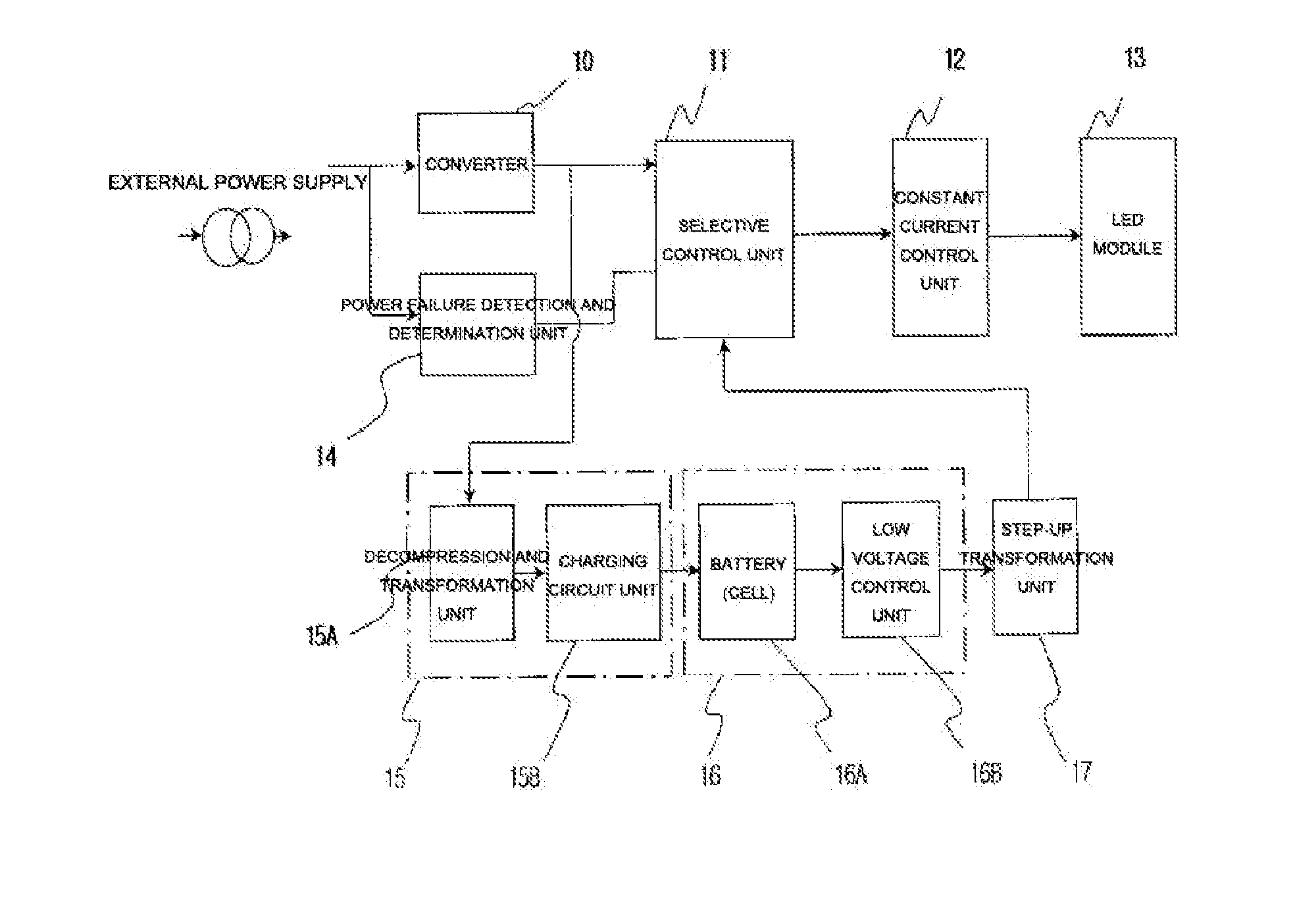
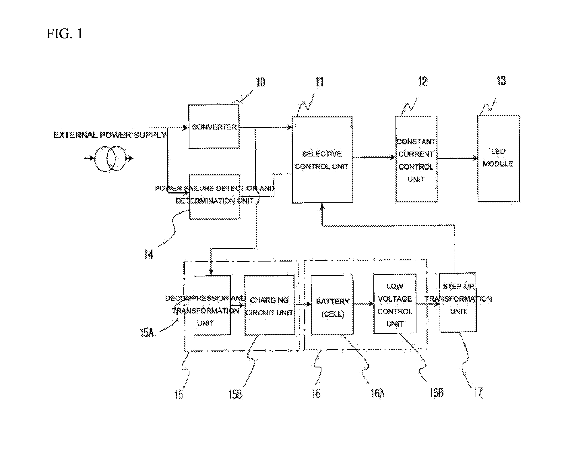
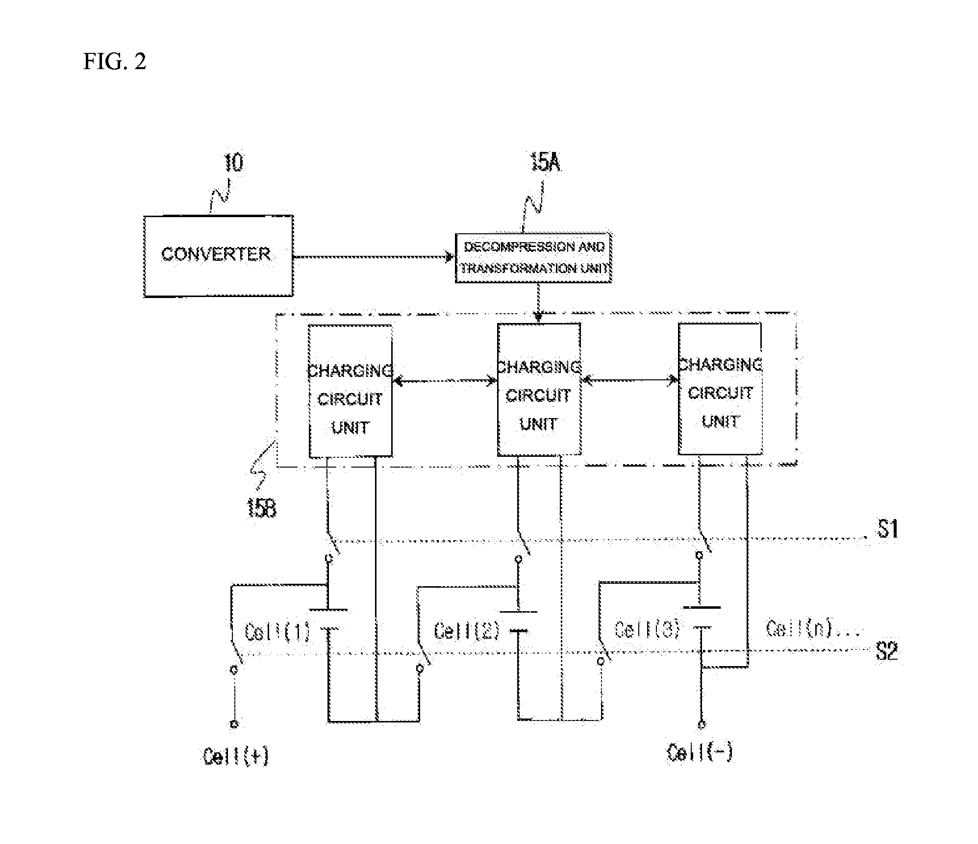
The present invention provides a charging system and power failure detecting device for LED lights. The charging system improves charging efficiency by dividing the power storage unit into cells, while the power failure detecting device can dynamically determine power failure based on output value and has no need for a separate ground wire. The system can also have an effect in case of power failure in building or various disasters, as it can determine the time when power failure is continuous and install the power failure detecting system by only the internal wire of the lighting fixture as a single-phase two wire system.

Problems solved by technology

The aforementioned disadvantage occurs due to a problem in a battery and a charging system as a major cause and in more detail, since excessive charging is continued in normal times in order to ensure a full charging state of the battery at the time when the emergency lighting device needs to be turned on, the life-span of the battery is extremely shorter than that of a battery used in a general electrical product.
Therefore, when other situations such as the power failure, and the like in which the emergency lighting device needs to be actually used occurs within a predetermined time after initial installation of the emergency lighting device, the emergency lighting device cannot normally perform its own function due to the aforementioned cause.

Method used


Image

  • Charging system and power failure device detecting power failure of LED light
  • Charging system and power failure device detecting power failure of LED light
  • Charging system and power failure device detecting power failure of LED light

Examples


Embodiment Construction

Technical Problem

[0005]The present invention is provided to solve the technical problems, secondary batteries used in the lighting device generally use a lithium-ion battery, a lithium-polymer battery, a lead battery, a nickel-hydride battery, a nickel-cadmium battery, and the like, and a lithium-iron phosphate battery and a hybrid battery have been newly used. Due to a characteristic of the secondary battery, since the secondary battery is prepared so that a withstand voltage per cell is generally less than 2.3 V to 4.5 V, if an output voltage of an internal converter or an inverter is stored in the LED light, a plurality of power storage units are connected to each other in series within a withstand-voltage available range (e.g. when a withstand of one battery is 2.5 V and the converter output voltage is 15 V, six or more power storage units are connected to each other in series), and even in the case of using an electric double-layer capacitor (EDLC), the secondary battery has be...


PUM


Abstract

In an emergency lighting apparatus, charging efficiency is increased by individually charging cells in a power storage unit. When a power failure or other situation occurs requiring the actual use of the emergency lighting device, the proper operation of the emergency lighting device is ensured. In particular, the disadvantage of additional wiring in a bulb-type lighting fixture and the disadvantage of grounding are addressed so that power can be continuously supplied to the emergency lighting device and the emergency lighting device functions properly.

Description

TECHNICAL FIELD[0001]The present invention relates to a charging system and a power failure detecting device of an LED light, and more particularly, to a charging system and a power failure detecting device of an LED light that overcome various problems occurring when secondary batteries are used and perform high-speed charging within a short time so that an emergency lighting device may be easily used in an actual emergency to ensure a human's view in an emergency, by using various secondary batteries as storage batteries used in a lighting device.BACKGROUND ART[0002]In general, installation of emergency lighting devices that enable preparing for a state of emergency such as a power failure has obligated in workplaces such as large buildings or public places in addition to lighting devices which are fundamentally installed. The emergency lighting devices are designed to be turned on and in this case, secondary batteries primarily used as power supplies of the emergency lighting dev...

Claims


Application Information

Patent Timeline
Patent Type & Authority Applications(United States)
IPC IPC(8): H02J9/06H02J7/00H05B33/08H05B44/00
CPCH02J9/061H05B33/0884H02J7/0068H05B33/0845H02J7/0018H05B45/50H05B45/37H02J7/04H02J7/35H02J7/0024H02J7/02H02J9/065H02J2207/20H02J7/007194Y02B10/70Y02B20/30Y02B20/40H05B47/13H02J7/007182F21S9/03H05B47/11H05B47/105
Inventor PARK, SEONGHOON
Owner PARK SEONGHOON
Learn More