Multiphase Power Converter Circuit and Method

a converter circuit and multi-phase technology, applied in the direction of dc-ac conversion without reversal, efficient power electronics conversion, climate sustainability, etc., can solve the problems of high dc voltage and converters have a disadvantage in terms of efficiency

Active Publication Date: 2015-01-15
INFINEON TECH AUSTRIA AG
View PDF3 Cites 57 Cited by
  • Summary
  • Abstract
  • Description
  • Claims
  • Application Information

AI Technical Summary

Problems solved by technology

High DC voltages, however, are critical in terms of the occurrence of electric arcs.
However, due to the large difference between input and output voltages these converters have a disadvantage in terms of efficiency.

Method used


Image

  • Multiphase Power Converter Circuit and Method
  • Multiphase Power Converter Circuit and Method
  • Multiphase Power Converter Circuit and Method

Examples


first embodiment

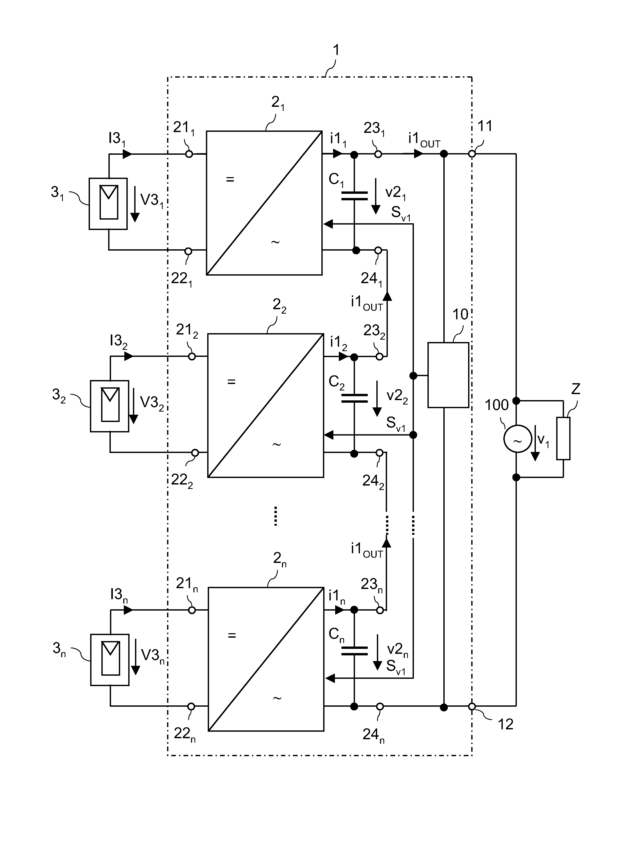
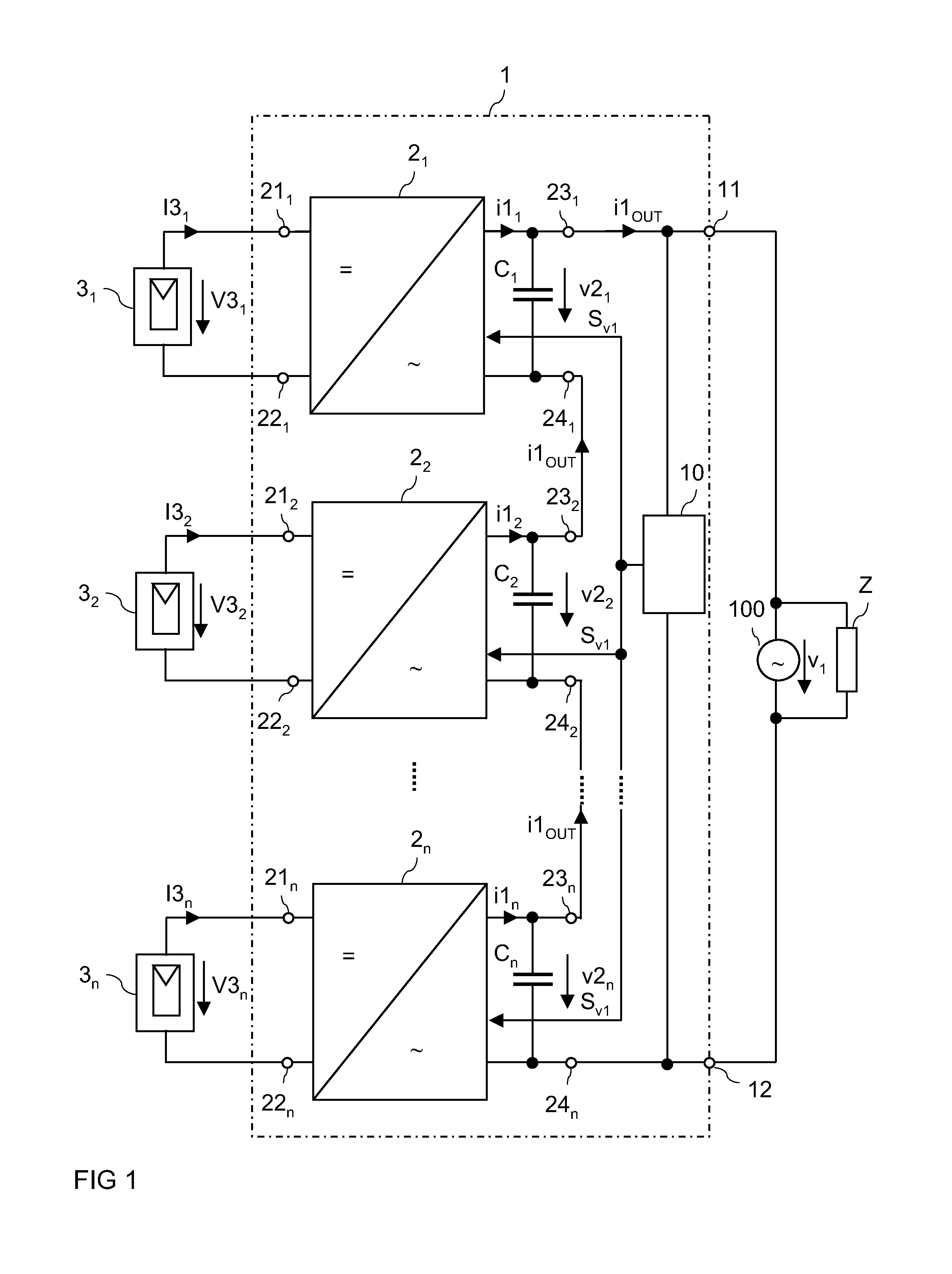
[0084]FIG. 1 illustrates a power converter circuit (power inverter circuit) 4 for converting a plurality of n (at least two) DC input voltages V31, V32, V3n into one AC output voltage v1 and one AC output current iOUT, respectively. It should be noted in this connection that throughout the drawings DC voltages and DC currents will be denoted using capital letters “V” and “I,” while AC voltages and AC currents will be denoted using lowercase letters “v” and “i.” The power converter circuit includes a plurality of n (at least two) converter units (inverter units) 21, 22, 2n, with n≧2. Each of these converter units includes an input with input terminals 211, 221; 212, 222; and 21n, 22n that are configured to be coupled to a DC power source 31, 32, 3n. In FIG. 1, besides the power converter circuit 1 with the converter units 21, 22, 2n DC power sources 31, 32, 3n are also illustrated. These DC power sources 31, 32, 3n together with the power converter circuit 1 form an AC power supply s...

second embodiment

[0221]a start-up sequence (start-up sequence B) is illustrated in FIG. 34. In this embodiment, the operation mode controller 50 leaves the series circuit 21-2n, connected to the output terminals 11, 12 when the power converter circuit 1 is in the standby mode. The individual converter units 2 are deactivated, so that the output current iOUT is zero and the output voltage vOUT corresponds to the external AC voltage v1. The external AC voltage v1 charges the input capacitor of the DC / AC converter 4, which is the DC link capacitor when a DC / DC converter 6 and a DC / AC converter 4 are employed. The charging of the input capacitor of the DC / AC converter 4 is explained for the DC / AC converter topologies of FIGS. 6 and 19 below. Referring to FIG. 6, the switches of the H4-bridge each have a freewheeling element 421-424. Via these freewheeling elements the input capacitor 41 (or the DC link capacitor 600 of FIG. 11) is charged to the peak value of the AC voltage v2 between the output termina...


PUM


Abstract

A multiphase power converter circuit includes at least two single phase power converter circuits. Each single phase power converter circuit includes at least one converter series circuit with a number of converter units. The converter series circuit is configured to output a series circuit output current. A synchronization circuit is configured to generate at least one synchronization signal. At least one of the converter units is configured to generate an output current such that at least one of a frequency and a phase of the output current is dependent on the synchronization signal.

Description

TECHNICAL FIELD[0001]Embodiments of the present invention relate to a power converter circuit, a power supply system with a power converter circuit, and a method for operating a power converter circuit.BACKGROUND[0002]With an increasing interest in sustainable energy production there is a focus on using photovoltaic modules for producing electric power. Photovoltaic (PV) modules include a plurality of photovoltaic (PV) cells, that are also known as solar cells. Since the output voltage of one cell is relatively low, a PV module usually includes a string with a plurality of series connected solar cells, such as between 50 to 100 cells connected in series, or even several such strings connected in parallel.[0003]A PV module provides a DC supply voltage, while power grids, such as national power grids, have an AC supply voltage. In order to supply the energy provided by a PV module to the power grid it is, therefore, necessary to convert the DC voltage of the PV module into an AC volta...

Claims


Application Information

Patent Timeline
Patent Type & Authority Applications(United States)
IPC IPC(8): H02M7/5387
CPCH02M7/53873H02M7/53871H02S40/00H02M1/007H02J3/381H02J2300/24H02J3/40H02M1/0043H02M7/4807H02J2300/10Y02E10/56H02M1/0077Y02B70/10H02M7/4815
Inventor DEBOY, GERALD
Owner INFINEON TECH AUSTRIA AG
Why Eureka
Try Eureka