Offline filtration device and method

a technology of filtration device and filter tube, which is applied in the direction of distillation regulation/control, pump control, vacuum distillation separation, etc., can solve the problems of water contamination sources, access panels, access panels, breathers or worn seals, and pressures and vacuums created within, etc., to achieve efficient use

Active Publication Date: 2015-01-15
PARKER HANNIFIN CORP
View PDF5 Cites 11 Cited by
  • Summary
  • Abstract
  • Description
  • Claims
  • Application Information

AI Technical Summary

Benefits of technology

[0009]In accordance with the present disclosure, an effective flow rate of the fluid being dehydrated is regulated based on temperature. An advantage of using temperature to determine the effective flow rate is more efficient use of heat energy. Further, regulating effective flow based on temperature in accordance with the present disclosure does not require the entire fluid reservoir to be heated and maintained a predetermined temperature, thus allowing operation of the system over a wider range of temperatures. As used herein, the term “predetermined” refers to values, setpoints, levels, etc. that are determined in advance and fixedly set within the controller, and values, setpoints, levels, etc. that can be dynamically changed, for example, based on operator input and / or calculations performed by an algorithm executed by a controller or the like.

Problems solved by technology

These hydraulic systems often create pressures and vacuums within the tank or reservoir during use.
For example, rain may leak into externally located reservoirs or seep through reservoir covers, access panels, breathers or worn seals.
Additionally, condensation from air in reservoirs and other system areas can be a source for water contamination.
Water in hydraulic fluid is undesirable for a number of reasons.
For example, water contamination can deplete some additives and react with others to form corrosive by-products which attack some metals.
In addition, water contamination can reduce lubricant film-strength, which leaves critical surfaces vulnerable to wear and corrosion, as well as reduce filterability, increase air entrainment ability and increase the likelihood of cavitation.
A problem with using moisture sensors, however, is that they tend to have slow response times (particularly when the fluid is above saturation), which can lead to less than optimal control of the dehydration process.

Method used


Image

  • Offline filtration device and method
  • Offline filtration device and method
  • Offline filtration device and method

Examples


Embodiment Construction

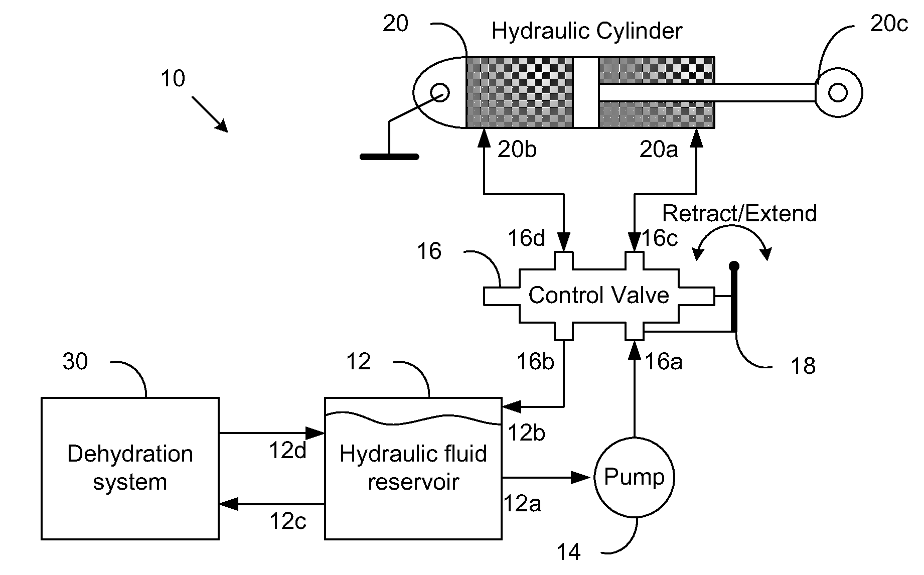
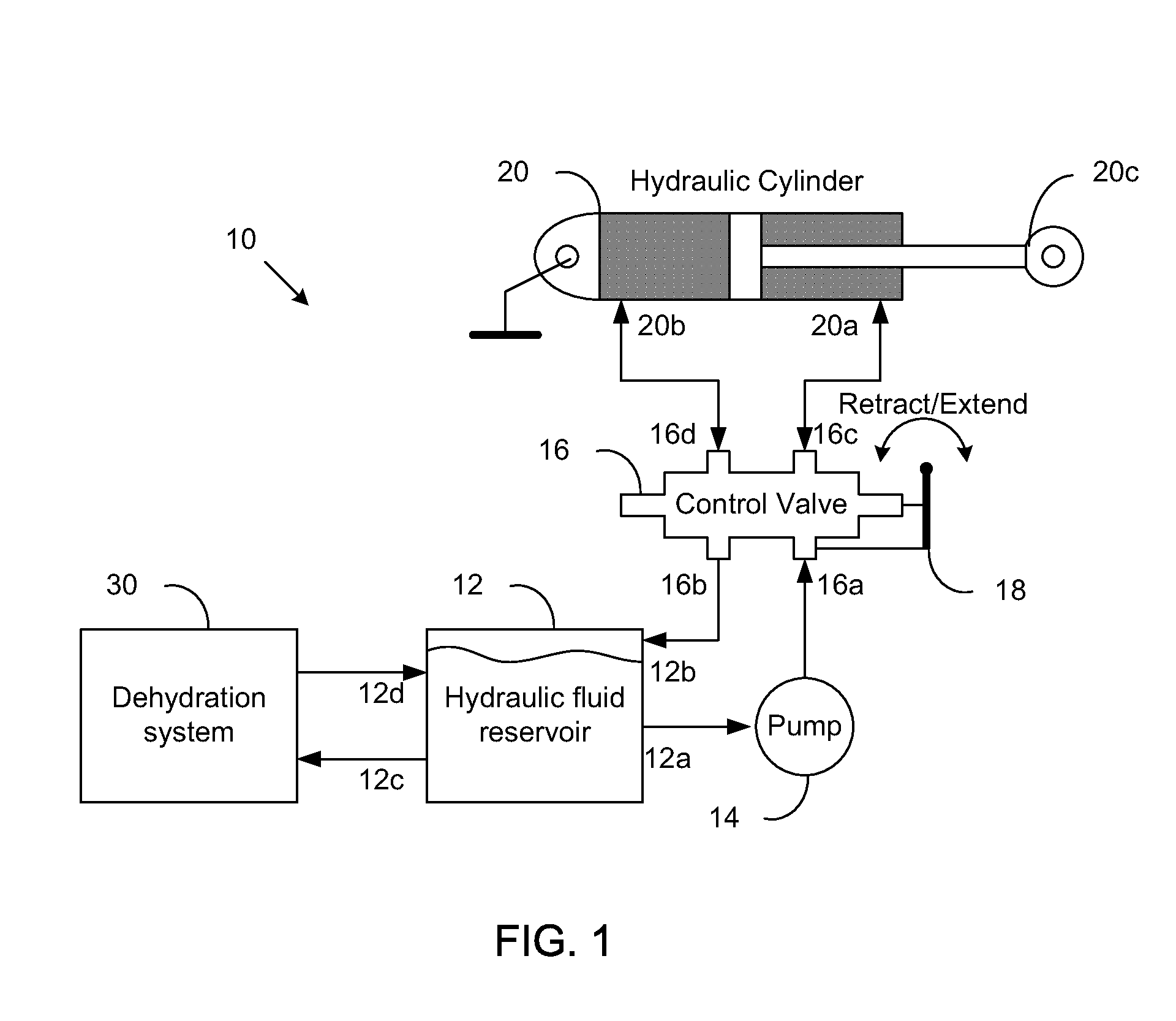
[0041]Referring now to the drawings in detail, and initially to FIG. 1, an exemplary hydraulic system is indicated generally by reference numeral 10. The hydraulic system 10 includes a hydraulic reservoir 12, which stores hydraulic fluid that is used to power hydraulic devices. As is known, hydraulic reservoirs hold excess hydraulic fluid to accommodate volume changes due to, for example, cylinder extension and contraction, temperature driven expansion and contraction, and leaks. As will be appreciated by one having ordinary skill in the art, the reservoir 12 may be sized to meet the requirements of the specific application.

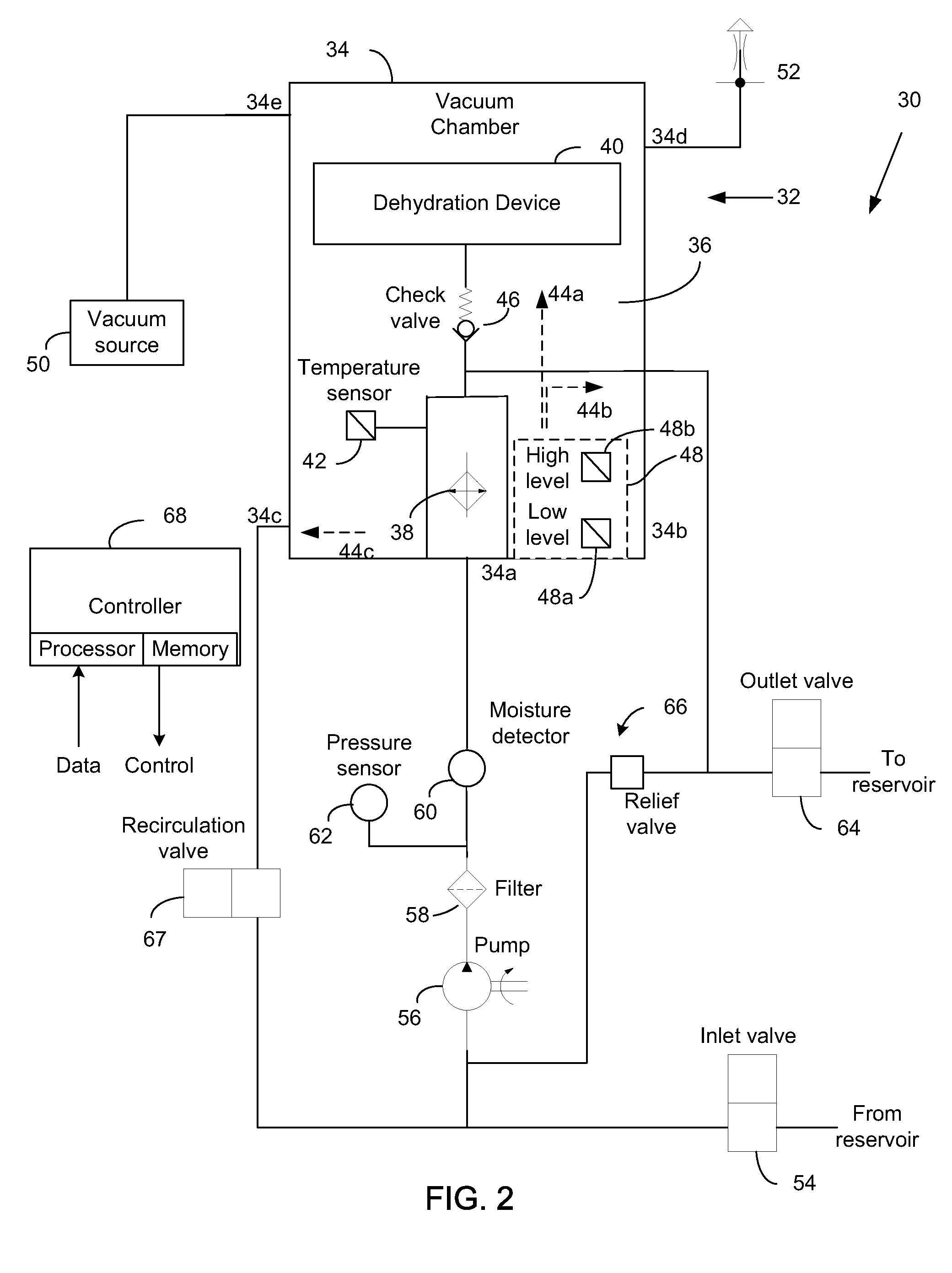
[0042]The reservoir 12 includes a system outlet 12a, which provides the hydraulic fluid to a pump 14 for pressurization, a system inlet 12b for return of the hydraulic fluid to the reservoir, a dehydration system outlet 12c for providing hydraulic fluid to a dehydration system, and a dehydration system inlet 12d for receiving dehydrated fluid from the dehydration...


PUM


Abstract

An apparatus, system and method are provided for controlling fluid flow through a vacuum chamber of a dehydration system, the vacuum chamber having a temperature sensing device operative to measure a temperature of a fluid in the vacuum chamber. A temperature difference between a temperature setpoint for the fluid and the measured temperature of the fluid is determined, and fluid is recirculated through the vacuum chamber while the temperature difference is greater than a predetermined temperature difference. While the temperature difference is less than the predetermined temperature difference, the fluid is recirculated through the vacuum chamber for a predetermined time period, and upon the predetermined time period expiring inhibiting recirculation of the fluid through the vacuum chamber.

Description

RELATED APPLICATION DATA[0001]This application claims the priority of US Provisional Application No. 61 / 844,921, filed on Jul. 11, 2013, which is hereby incorporated by reference in its entirety.FIELD OF THE INVENTION[0002]The present invention relates generally to fluid dehydration, and more particularly to an apparatus and method for controlling vacuum dehydration of a fluid based on temperature.BACKGROUND[0003]Certain hydraulic systems include a tank or reservoir that receives and stores hydraulic fluid. These hydraulic systems often create pressures and vacuums within the tank or reservoir during use. Breather vents are typically provided in the tank to ensure that uncontaminated air is provided into the system and that the proper pressures are maintained for efficient and safe operation of the system.[0004]For various reasons, water may find its way into the hydraulic fluid. For example, rain may leak into externally located reservoirs or seep through reservoir covers, access p...

Claims


Application Information

Patent Timeline
Patent Type & Authority Applications(United States)
IPC IPC(8): F04B49/00
CPCF04B49/002B01D3/42B01D3/10B01D17/02B01D17/12C10G7/04C10G33/08
Inventor TROTT, JOHN A.
Owner PARKER HANNIFIN CORP
Why Eureka
Try Eureka