Self-aligned tunable metamaterials

a metamaterial and self-aligning technology, applied in the direction of printing, crystal growth process, chemically reactive gas, etc., can solve the problems of limited methods of forming periodic and spatially indexed nanoscale arrays of metamaterials, such as ion beam methods, and poorly suited to widespread industrial application

a metamaterial and self-aligning technology, applied in the direction of printing, crystal growth process, chemically reactive gas, etc., can solve the problems of limited methods of forming periodic and spatially indexed nanoscale arrays of metamaterials, such as ion beam methods, and poorly suited to widespread industrial application

US20150017466A1Inactive Publication Date: 2015-01-15AYON ARTURO A +2

Image

  • Self-aligned tunable metamaterials
  • Self-aligned tunable metamaterials
  • Self-aligned tunable metamaterials

Examples


Embodiment Construction

)

[0012]Various types of metamaterials are known that possess bulk electromagnetic properties different from materials observed in nature. These properties may create specific dispersion characteristics within the metamaterial, or they may control the way the metamaterial reflects, refracts, absorbs, scatters or transmits radiation.

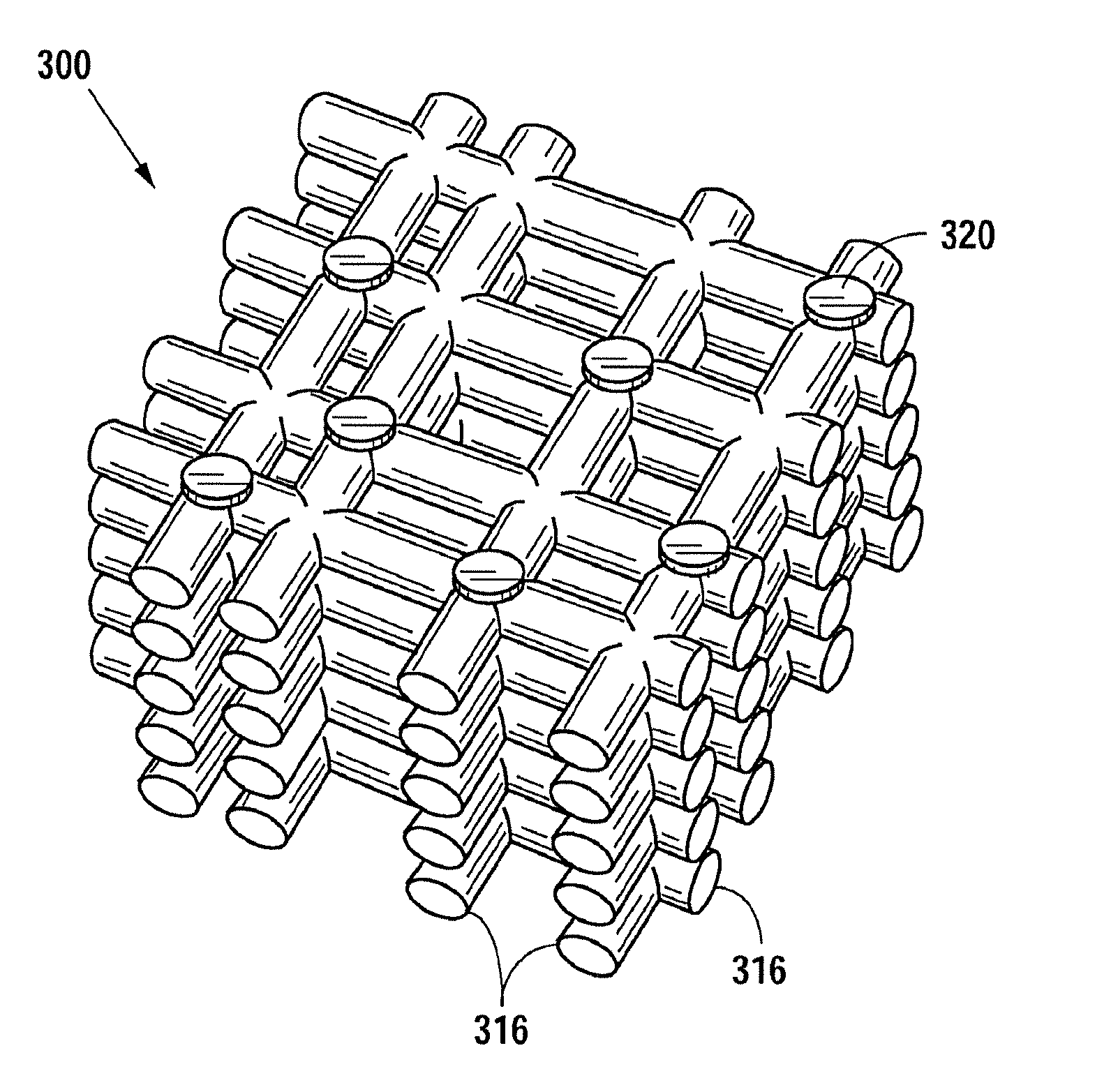
[0013]Metamaterials are also known that direct electromagnetic radiation. The ability to direct radiation can result from an outer form or shape of a given material, for example, as in a conventional lens. Another way to control the path of radiation can result from the internal structure of a material. Spatial indexing, as used herein, refers to a patterned structure of a material that enables tuning of the electromagnetic properties of the material in space. For example, the geometry of an array structure and / or the constituent material composition may be varied in space. In one embodiment, a smooth increase of an array periodicity in a given direction m...


PUM

PropertyMeasurementUnit
Depthaaaaaaaaaa
Metallic bondaaaaaaaaaa
Frequencyaaaaaaaaaa

Abstract

A self-aligned tunable metamaterial is formed as a wire mesh. Self-aligned channel grids are formed in layers in a silicon substrate using deep trench formation and a high-temperature anneal. Vertical wells at the channels may also be etched. This may result in a three-dimensional mesh grid of metal and other material. In another embodiment, metallic beads are deposited at each intersection of the mesh grid, the grid is encased in a rigid medium, and the mesh grid is removed to form an artificial nanocrystal.

Description

BACKGROUND[0001]1. Field of the Disclosure[0002]This disclosure relates to the field of tunable metamaterials, and more particularly to self-aligned arrays of nanomaterials.[0003]2. Description of the Related Art[0004]Metamaterials are synthetic, composite materials with periodic structures, known for their ability to create electromagnetic or acoustic properties that are not found in nature and that may determine how the material interacts with various types of radiation. Metamaterials may direct radiation either due to the external shape of a metamaterial structure or by spatially indexing the metamaterial. Conventional methods of forming metamaterial periodic and spatially indexed arrays in the nanoscale range, such as ion beam methods, are limited by processing options, materials, and ultimately, economic feasibility, and may be poorly suited to gain widespread industrial applicability. Therefore, there is a need in the art for an industrial method of producing desired tunable n...

Claims


Application Information

Patent Timeline
15 Jan 2015
Publication
US20150017466A1
IPC
C30B19/12; C30B23/02; C30B19/06; C30B30/02; C30B29/66; C30B29/68; C30B29/58; C30B29/52; C30B19/10; C30B23/08
CPC
C30B19/06; C30B19/103; C30B29/66; C30B19/12; C30B30/02; C30B29/68; C30B23/025; C30B23/08
Inventors
AYON, ARTURO A.; KOTHA, RAMAKRISHNA