Metallic housing of electronic device and manufacturing method thereof

a technology of electronic devices and metal housings, which is applied in the direction of electrical apparatus casings/cabinets/drawers, foundry patterns, foundry moulding apparatus, etc., can solve the problems of complex manufacturing procedures and high cos

Inactive Publication Date: 2015-01-22
FU ZHUN PRECISION IND SHENZHEN +1
View PDF7 Cites 19 Cited by
  • Summary
  • Abstract
  • Description
  • Claims
  • Application Information

AI Technical Summary

Problems solved by technology

However, the manufacturing proc

Method used


Image

  • Metallic housing of electronic device and manufacturing method thereof
  • Metallic housing of electronic device and manufacturing method thereof
  • Metallic housing of electronic device and manufacturing method thereof

Examples


Embodiment Construction

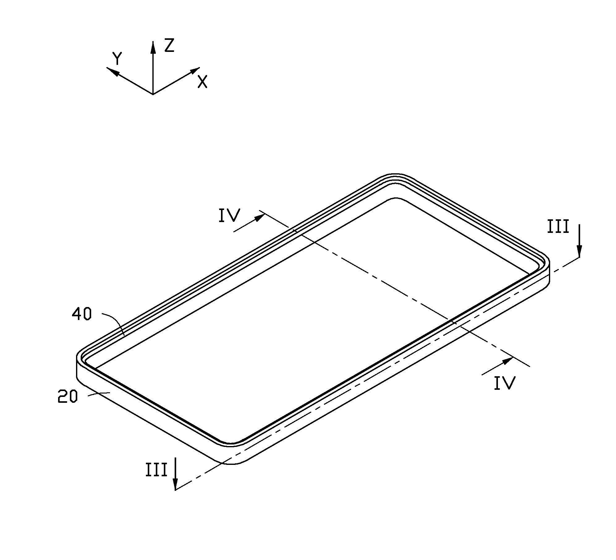
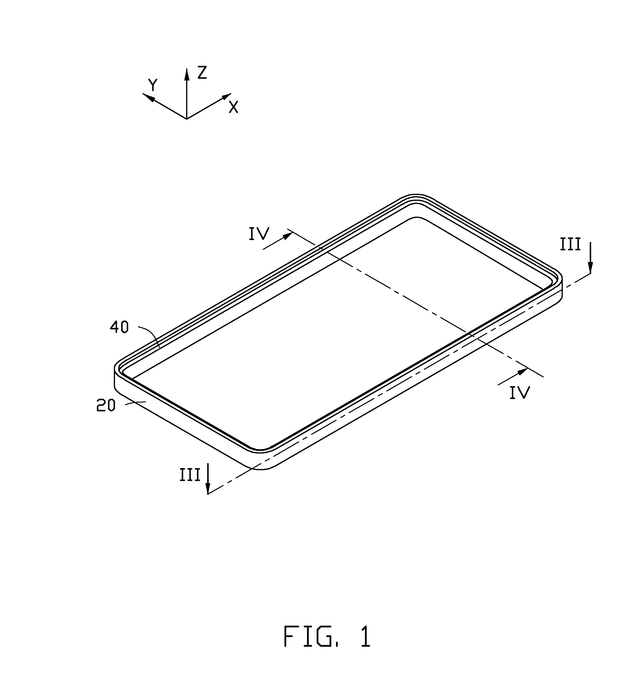
[0013]Referring to FIGS. 1 through 3, an embodiment of a metallic housing 100 in an electronic device (not shown) includes an outer frame 20 and an inner structural member 40. The inner structural member 40 is received within the outer frame 20 and is inset on an inner surface 22 of the outer frame 20.

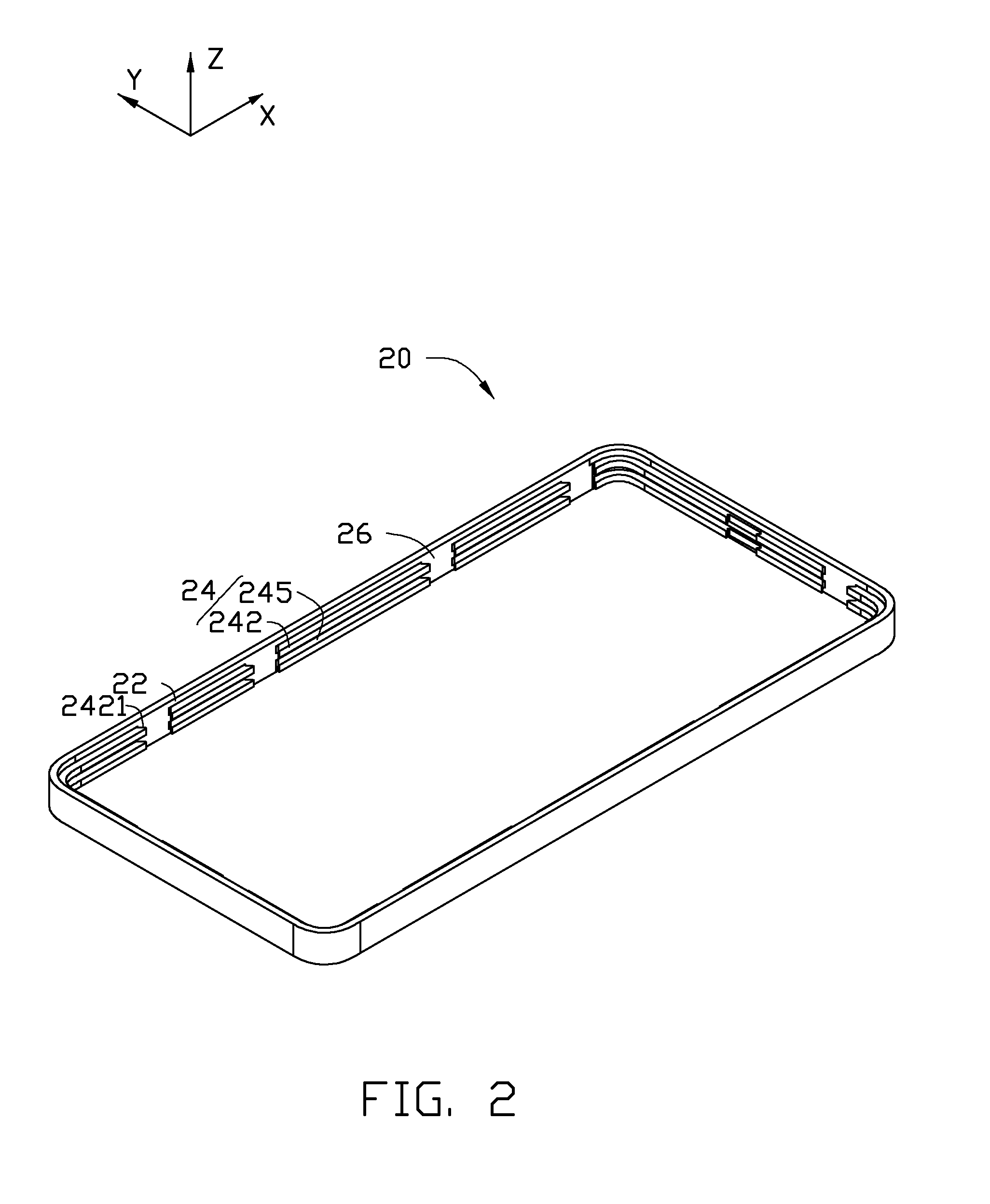
[0014]Also referring to FIG. 4, the outer frame 20 is substantially rectangular. The outer frame 20 includes a plurality of latching portions 24 and defines a plurality of latching grooves 26. The plurality of latching portions 24 are arranged on the inner surface 22 along an extending direction of the outer frame 20. The latching portions 24 are spaced from each other, thereby forming the plurality of latching grooves 26 inbetween. Each latching portion 24 includes a pair of protruding latching ribs 242 and a receiving groove 245 defined between the pair of latching ribs 242. The pair of latching ribs 242 are substantially parallel to each other. The pair of latching ribs 242 extends ...


PUM

PropertyMeasurementUnit
Temperatureaaaaaaaaaa
Shapeaaaaaaaaaa
Metallic bondaaaaaaaaaa

Abstract

A metallic housing of an electronic device, includes a metallic outer frame and an inner structural member. The metallic outer frame comprises a plurality of latching portions protruding, and a plurality of latching grooves. The inner structural member is made from metal-alloy and embedded in the outer frame by die-casting. The inner structural member comprises a peripheral sidewall, a plurality of engaging portions, and a plurality of matching portions. The plurality of engaging portions and the plurality of matching portions protrude from the peripheral sidewall outwardly. Each latching portion comprises at least two parallel latching ribs, and forms a receiving groove between two adjacent latching ribs. The plurality of engaging portions is respectively embedded in the plurality of receiving grooves, and the plurality of matching portions is respectively embedded in the plurality of latching grooves. The present disclosure further provides a manufacturing method for the metallic housing.

Description

BACKGROUND[0001]1. Technical Field[0002]The present disclosure relates to a housing of an electronic device and a manufacturing method thereof, and more particularly to a metallic housing of an electronic device and a manufacturing method thereof.[0003]2. Description of Related Art[0004]Magnesium alloy, aluminum alloy, and zinc alloy are often used to make housings of electronic devices, due to their light weight, high scalability, easy molding, and high structural strength. Because metal-alloys do not possess the attractive metallic appearance of pure metals, a metallic layer is coated onto an outer surface of the housing to enhance the metallic appearance. However, the manufacturing procedure is complex and expensive.[0005]Therefore, there is room for improvement in the art.BRIEF DESCRIPTION OF THE DRAWINGS[0006]The components in the drawings are not necessarily drawn to scale, the emphasis instead placed upon clearly illustrating the principles of the present disclosure. Moreover...

Claims


Application Information

Patent Timeline
IPC IPC(8): B22D19/00H05K5/04B22D17/22
CPCB22D19/00B22D17/2218H05K5/04B22D17/00B22D19/04H05K5/0243B22D19/16B22C9/108B22C9/22B22D17/005B22D17/02B22D21/007B22D25/02B22D29/00H05K5/0217
Inventor WANG, CAI-HUALI, YUE-JIANLIN, CHEN-SHENCHANG, WEN-HSIUNGCHANG, CHUN-JUNG
Owner FU ZHUN PRECISION IND SHENZHEN
Why Eureka
Try Eureka