Handheld device

a hand-held device and antenna technology, applied in the direction of antenna details, elongated active element feed, antennas, etc., can solve the problems of increasing the complexity of the antenna design, affecting the operation efficiency of the antenna, and the inability of the conventional single-frequency band pifa to operate in multiple central frequency bands through switching operations, etc., to achieve the effect of small volume, simple design and small volum

Active Publication Date: 2015-01-22
HTC CORP
View PDF3 Cites 48 Cited by
  • Summary
  • Abstract
  • Description
  • Claims
  • Application Information

AI Technical Summary

Benefits of technology

[0007]An objective of the subject application is to provide a handheld device, which has a small volume and a simple design and can adaptively operate at two different central frequency bands. Because a planar antenna of the subject application only has a metal layer patterned on a housing of the handheld device as a radiator, the planar antenna will have a reduced volume as compared to that of the conventional single-frequency band PIFA antenna. Furthermore, because the planar antenna of the subject application is able to operate at two central frequency bands without need of other additional parasitic antenna elements and / or other branches, complexity in design of the planar antenna is also reduced.

Problems solved by technology

Furthermore, to operate in different central frequency bands, the conventional single-frequency band PIFA will, due to the increased number of antenna elements, suffer from an unexpected coupling effect between the antenna elements, which may lead to increased complexity in the antenna design.
Also due to the increased number of antenna elements, the antenna is made to have a bulky volume, thereby giving rise to a lot of unfavorable factors.
On the other hand, the conventional single-frequency band PIFA is also unable to operate in multiple central frequency bands through switching operations.

Method used


Image

  • Handheld device
  • Handheld device
  • Handheld device

Examples


first embodiment

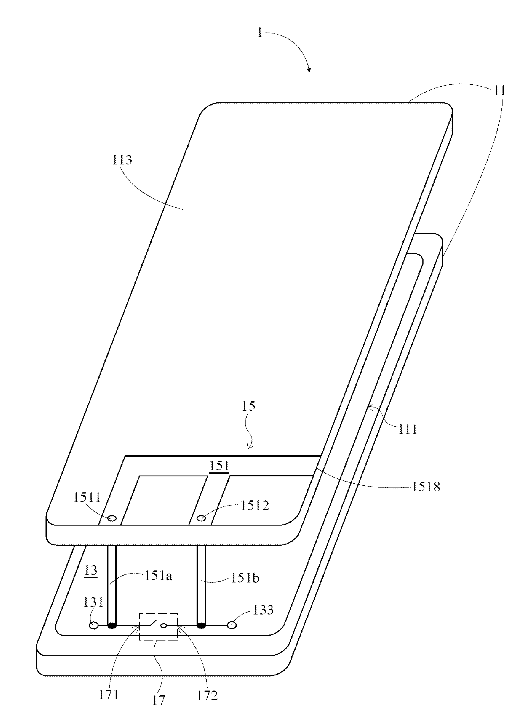
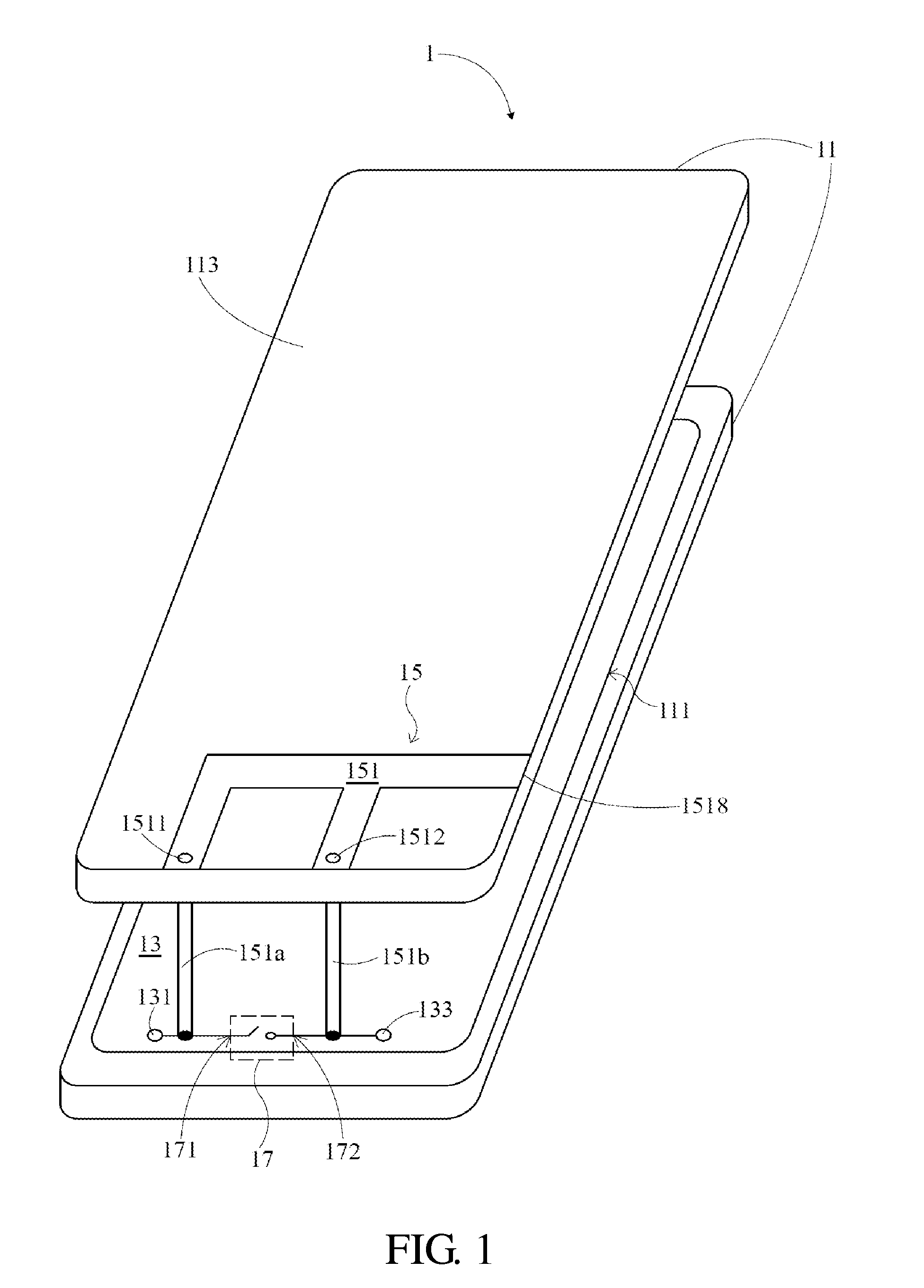
[0018]FIG. 1 depicts a handheld device 1 according to the present invention. The handheld device 1 may be a mobile phone, a notebook computer, a tablet computer, a wireless router or some other device that needs to operate at multiple frequency bands. The handheld device 1 comprises a housing 11, a circuit board 13, a planar antenna 15 and a switch 17. It shall be noted that, for purpose of simplicity of the description, other components of the handheld device 1 such as the display module, the communication module, the input module, the power supply module and other components less related to the subject application will be omitted from depiction herein. Furthermore, the planar antenna 15 of the subject application may also be applied to various communication systems, e.g., the Code Division Multiple Access (CDMA) system, the 3GPP Long Term Evolution (LTE) system, the Global System for Mobile Communication (GSM), the Digital Communication System (DCS), the Personal Communications Se...

third embodiment

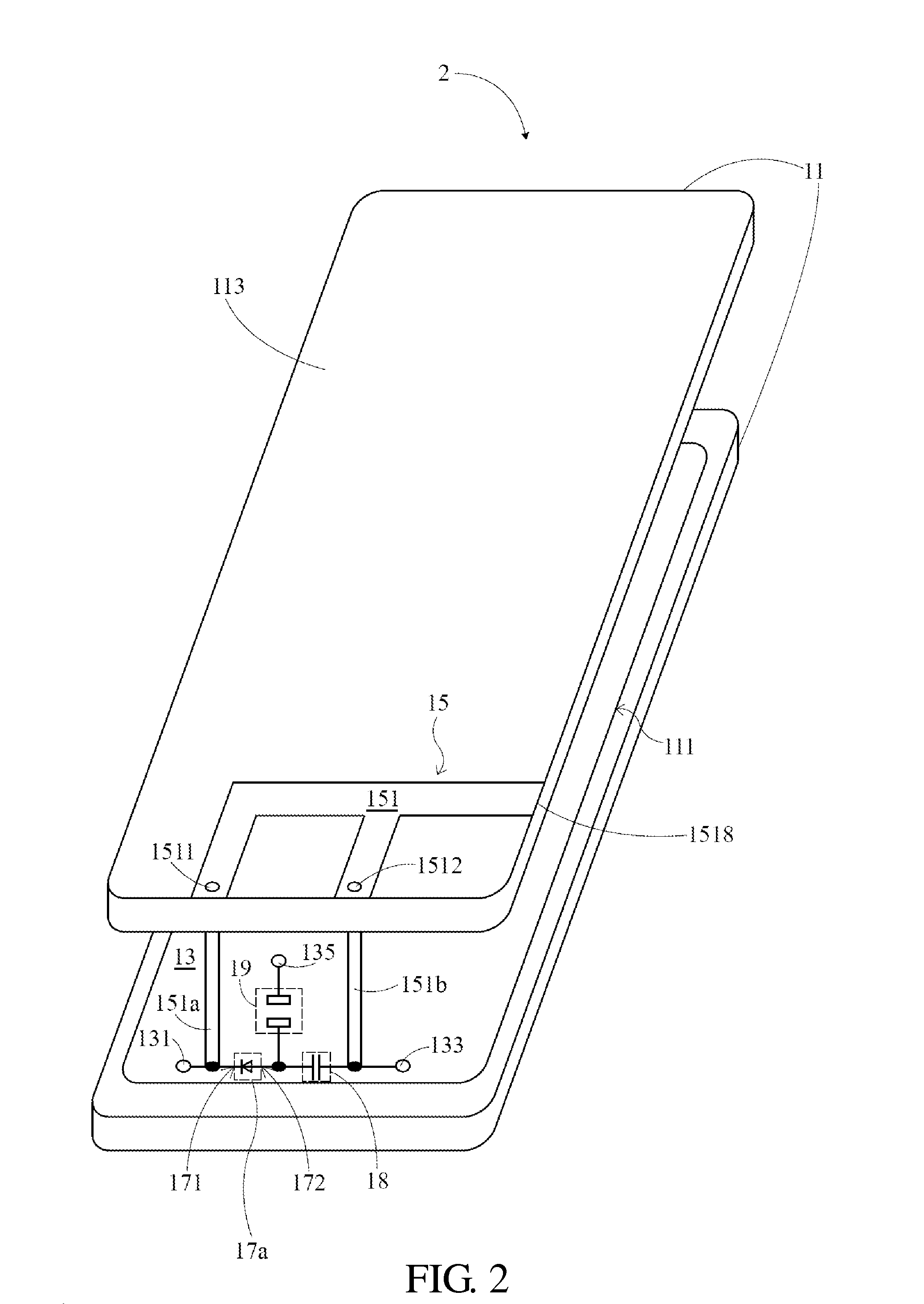
[0030]Similarly, in the third embodiment, the switch 17 is also a diode element 17a. The first electrode 171 of the diode element 17a is electrically connected to the first connecting point 1511 of the metal layer 151 via the grounding connector 151a, and the second electrode 172 of the diode element 17a is electrically connected to the third connecting point 1513 of the metal layer 151 via the first connector 151c. The third connecting point 1513 is further electrically connected via the second connecting point 1512, the feeding connector 151b and the RF blocking element 19 to a DC signal terminal 135 of the circuit board 13 to receive a DC signal. The DC signal is transmitted through the first connector 151c to the diode element 17a along the path described above, and is configured to control whether to turn on or turn off the diode element 17a.

[0031]A handheld device 4 of a fourth embodiment of the present invention is as shown in FIG. 4. Different from the second embodiment, th...

sixth embodiment

[0037]When the switch 17 is turned off, the planar antenna 15 can operate at a second central frequency band, which comprises a second low-frequency current path and a second high-frequency current path. The second low-frequency current path only extends from the grounding terminal 131 through the grounding connector 151a to the first connecting point 1511 and then to the endpoint 1518. The second high-frequency current path extends also from the grounding terminal 131 through the grounding connector 151a to the first connecting point 1511 and then through the second connecting point 1512 to the endpoint 1517. Similarly, when the diode element 17a is turned off, a dual-band operating mode of the planar antenna 15 can be achieved. Accordingly, the handheld device 6 of the sixth embodiment has four operating-frequency modes in total.

[0038]For example, FIG. 7 is a schematic view illustrating a voltage standing wave ratio (VSWR) of the handheld device 6 according to the sixth embodiment...


PUM


Abstract

A handheld device is provided, wherein the handheld device comprises a housing, a circuit board, a planar antenna and a switch. The housing comprising an outer surface is configured to define a receiving space. The circuit board is disposed in the receiving space. The planar antenna comprises a metal layer, wherein the metal layer comprising a first connecting point and a second connecting point is patterned on the outer surface. The switch comprising a first electrode and a second electrode is configured to control the electrical connection between the first connecting point and the second connecting point, wherein the first electrode and the second electrode are electrically connected between the first connecting point and the second connecting point. The planar antenna operates at a first central band when the switch is turned on, and operates at a second central band when the switch is turned off.

Description

CROSS-REFERENCE TO RELATED APPLICATIONS[0001]This application is a divisional application of U.S. application Ser. No. 13 / 041,858 filed Mar. 7, 2011, the disclosure of which is incorporated herein in its entirety by reference.FIELD OF THE INVENTION[0002]The subject application relates to a handheld device. More particularly, a planar antenna of the handheld device of the subject application comprises a switch so that, by adaptively turning on or off the switch, the planar antenna can operate at two central frequency bands.DESCRIPTIONS OF THE RELATED ART[0003]Thanks to development of the communication industry, people can now communicate with or transmit data to each other through wireless transmissions. In recent years, as several kinds of wireless communication systems have been proposed and put into practice successively, most of mobile phones available in the market are able to support communications via two or more kinds of wireless communication systems. For example, mobile pho...

Claims


Application Information

Patent Timeline
Patent Type & Authority Applications(United States)
IPC IPC(8): H01Q1/24H01Q5/00H01Q5/10
CPCH01Q5/0041H01Q1/243H01Q5/364H01Q5/50H01Q9/42H04B1/006H04W88/02H01Q5/335H01Q1/24H04B1/38
Inventor CHEN, CHIEN-CHIHTSENG, CHUN-WEIKUO, YEN-LIANGCHEN, WAN-MING
Owner HTC CORP
Why Eureka
Try Eureka