Capacitive sensing apparatus and methods

Active Publication Date: 2015-01-22
TEXAS INSTR INC
View PDF2 Cites 12 Cited by
  • Summary
  • Abstract
  • Description
  • Claims
  • Application Information

AI Technical Summary

Benefits of technology

[0014]In some embodiments, the output waveform phase and amplitude are measured by performing analog-to-digital (“ADC”) conversions of the output waveform. A sampling clock used to clock the ADC may also be used to synchronize the waveform generator(s) used to generate the periodic input waveforms. A set of output waveform magnitude values sampled from portions of a cycle of a periodic input waveform is acted upon by a discrete Fourier transform (“DFT”) logic module associated with a waveform generator of a particular frequency. In some embodiments the DFT is a s

Problems solved by technology

Capacitive sensors and capacitive touch detection apparatus are traditionally susceptible to electromagnetic interference (“EMI”) due to their high impedance characteristics.
Such EMI may include power line noise, energy-saving lamp noise, noise from switchin

Method used


Image

  • Capacitive sensing apparatus and methods
  • Capacitive sensing apparatus and methods
  • Capacitive sensing apparatus and methods

Examples


Embodiment Construction

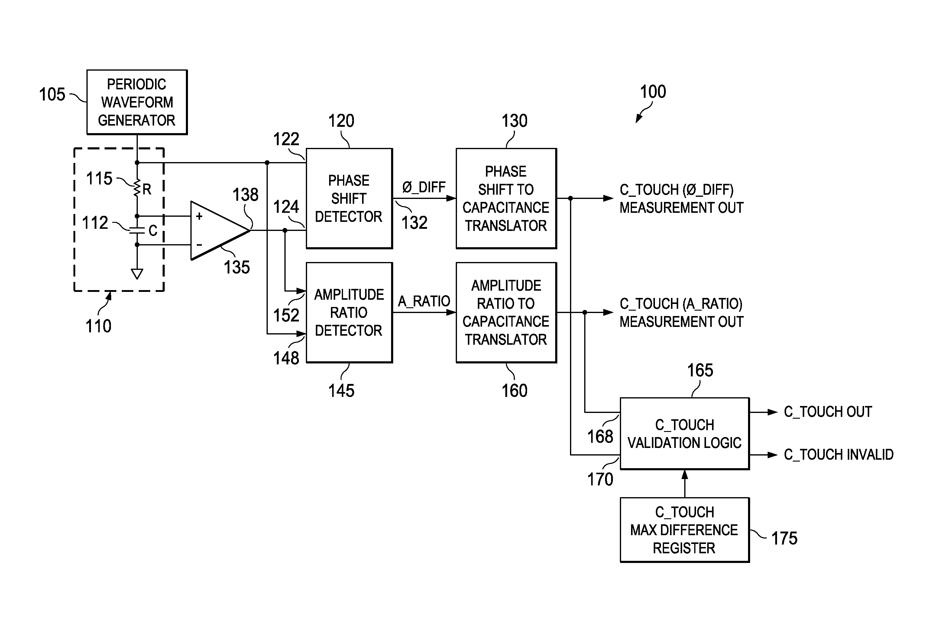
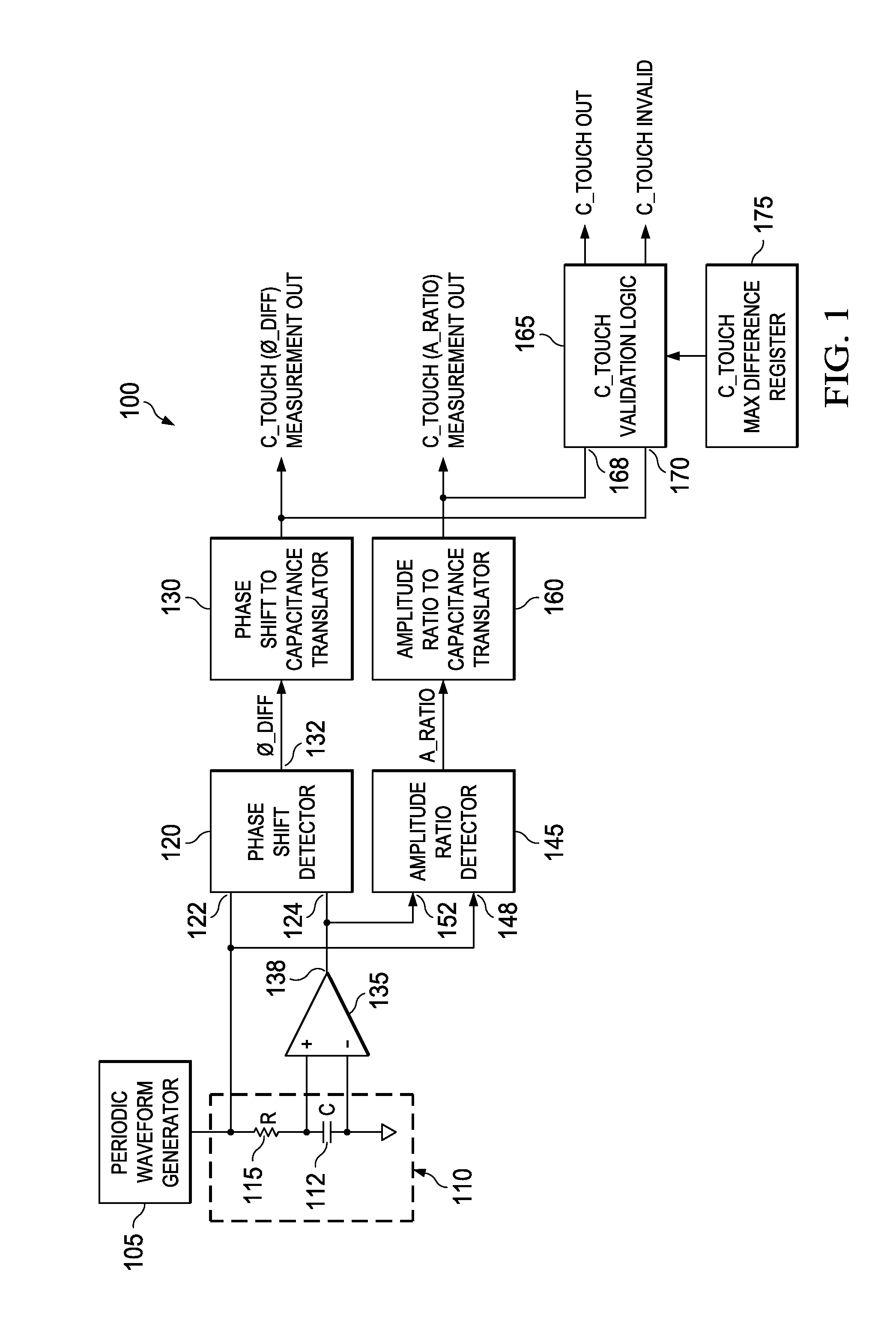
[0017]FIG. 1 is a schematic diagram of a capacitive touch detection apparatus 100 according to various example embodiments of the invention. The apparatus 100 includes a periodic waveform generator 105 coupled across a series-connected resistive-capacitive (“RC”) network 110. The periodic waveform generator 105 generates a periodic voltage waveform of frequency F and imposes the periodic voltage waveform across the RC network 110. The periodic waveform generator 105 may generate a sine waveform, a triangular waveform, a square waveform or a pulse waveform among other waveform shapes.

[0018]The RC network 110 includes a capacitive touch element C 112 of variable capacitance C_TOUCH and a resistor R 115. Values of the capacitance parameter C_TOUCH are a function of a proximity of a dielectric mass to C 112, among other factors.

[0019]The detection apparatus 100 also includes a phase shift detector 120. A first input 122 of the phase shift detector 120 is coupled across the RC network 11...


PUM


Abstract

One or more waveform generators impose an input waveform across touch sensor components. Phase shift detection logic measures a phase shift between the input waveform and an output waveform component associated with each waveform generator appearing across a touch sensor component. Amplitude ratio detection logic measures an output-to-input waveform magnitude ratio associated with each waveform generator. Translator logic converts the phase shift(s) and optionally the output-to-input waveform magnitude ratio(s) to capacitance values. Validation logic compares the resulting capacitance values to each other to determine consistency and validity during a particular waveform sampling time. The phase shift detection logic and the amplitude ratio detection logic are optionally implemented with discrete Fourier transform logic which includes narrow-band filtering to exclude electromagnetic interference frequency components from touch sensor signal measurements.

Description

PRIORITY CLAIM[0001]This application claims the benefit of priority under 35 U.S.C. §119(e) to U.S. Provisional Patent Application Ser. No. 61 / 856,335 titled “Robust Capacitive Sensing,” filed on Jul. 19, 2013 and to U.S. Provisional Patent Application Ser. No. 61 / 877,760 titled “Robust Capacitive Sensing” filed on Sep. 1, 2013, both incorporated herein by reference in their entirety.TECHNICAL FIELD[0002]Structures and methods described herein relate to capacitive touch sensing, including the generation, detection, and processing of capacitive sensor signals to achieve higher signal-to-noise ratios, greater sensitivity, and increased reliability of capacitance measurements in the presence of a background electromagnetic interference field.BACKGROUND INFORMATION[0003]Capacitive sensors utilize a conductive element and a proximate ground plane or one or more proximate conductive elements separated by a dielectric material to form one or more capacitive touch elements. Each capacitive ...

Claims


Application Information

Patent Timeline
IPC IPC(8): G06F3/044
CPCG06F3/044G06F3/0418G06F3/04182G06F3/04184
Inventor GOSSNER, KAI
Owner TEXAS INSTR INC
Why Eureka
Try Eureka