Light source system and projection system applied thereby

Active Publication Date: 2015-01-22
APPOTRONICS CORP LTD
View PDF6 Cites 6 Cited by
  • Summary
  • Abstract
  • Description
  • Claims
  • Application Information

AI Technical Summary

Benefits of technology

[0010]In a light source system according to the invention, by adjusting the position of the light spot with the adjusting device, the adjusted light spot of the excitation light on the moving device moves periodically along a second working track, and because the second working track is separate from a first working track of the unadjusted light spot, the load on the wavelength conversion materials along the first working track can be reduced, the aging of the wavelength conversion materials is slowed down, and the life of the light source device is increased. In another light source device of the

Problems solved by technology

This increases the area of illumination and lowers the power intensity of the excitation, solving the problem of reduced light conversion efficiency of the wavelength conversion material due to high temperature.
While such a system can

Method used


Image

  • Light source system and projection system applied thereby
  • Light source system and projection system applied thereby
  • Light source system and projection system applied thereby

Examples


first embodiment

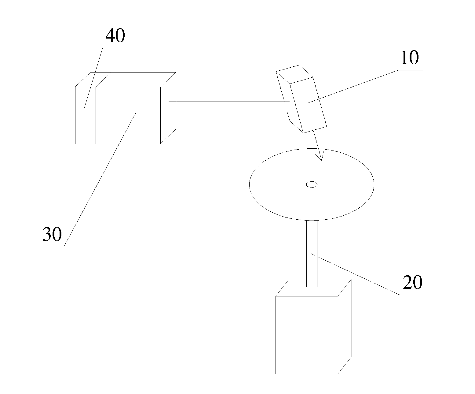
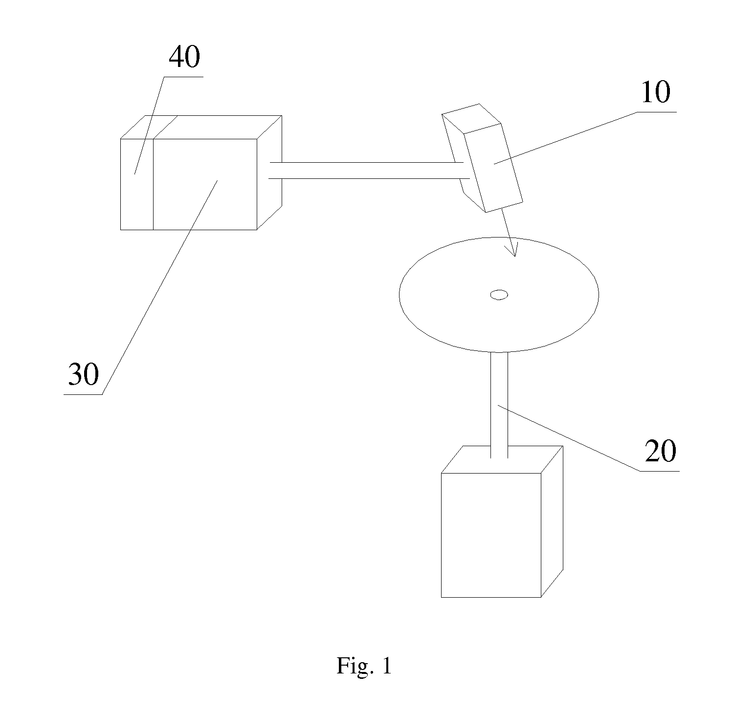
[0025]Refer to FIG. 1, which illustrates the structure of a light source system according to the present invention.

[0026]In this embodiment, the light source system includes a light source 10 for emitting an excitation light, and a moving device 20 carrying light wavelength conversion materials layers. The excitation light from the light source 10 illuminates the wavelength conversion materials. When the moving device 20 is in a periodic moving state, the light spot of the excitation light on the moving device 20 moves periodically along a first working track. The light source system further includes an adjusting device 30, which is used to adjust the light spot position when the moving device stops moving. After the light spot position is adjusted by the adjusting device 30, the moving device 20 is triggered to resume its periodic movement, so that the adjusted light spot of the excitation light on the moving device 20 moves periodically along a second working track. The first and ...

second embodiment

[0038]Refer to FIG. 3, which illustrates the structure of a light source system according to the present invention.

[0039]This embodiment is similar to the first embodiment, a difference being the adjusting device 30 is coupled to the moving device 20, to drive the moving device 20 to shift or rotate, so as to cause the light spot position to be displaced in a direction that intersect the first working track.

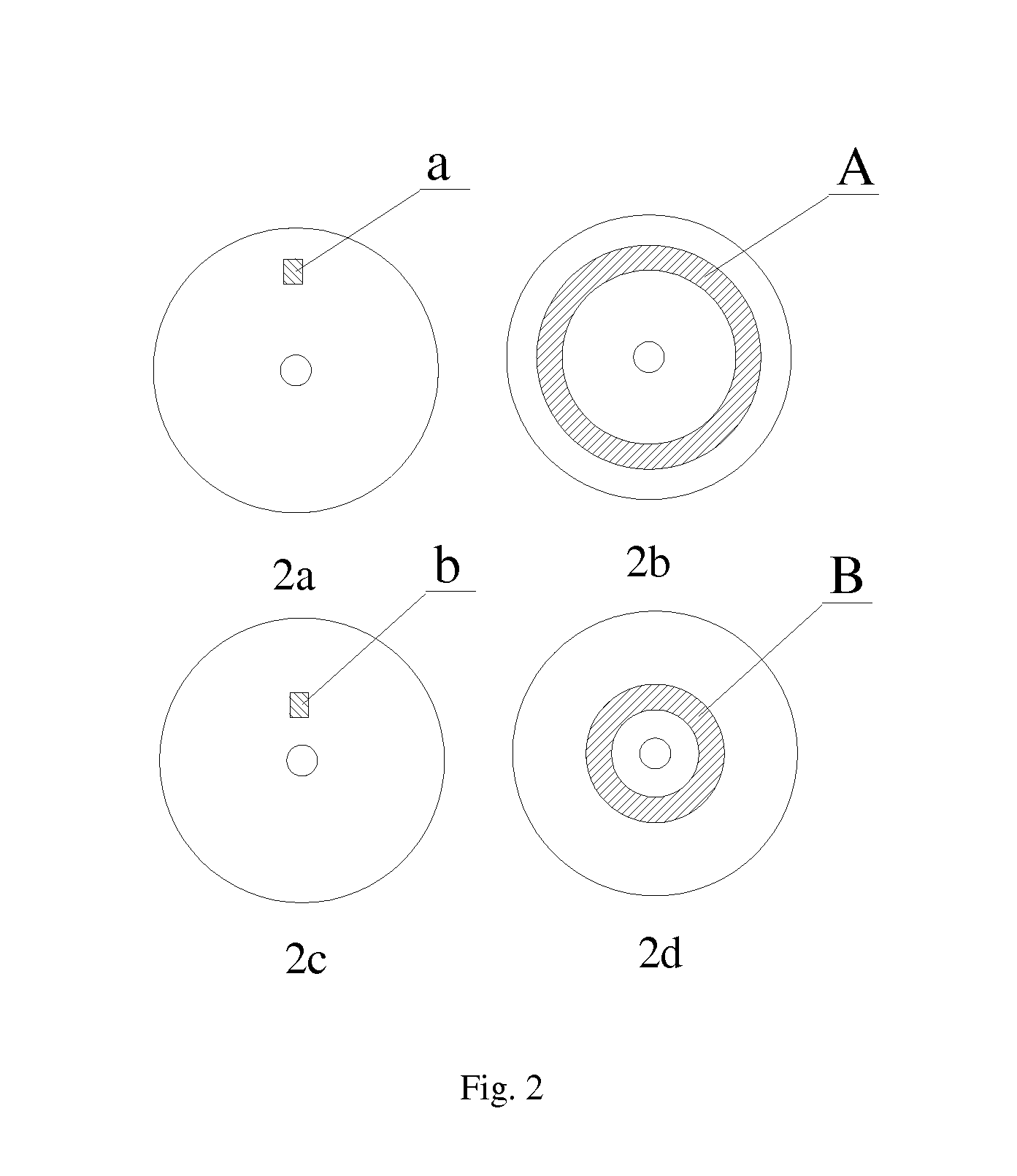
[0040]Taking a circular disk shaped moving device 20 as an example, in this embodiment, the adjusting device 30 can drive the moving device 20 to shift when the latter stops its periodic movement, so as to change the radial position of the light spot on the moving device, and then trigger the moving device to resume the periodic movement. This achieves the separation of the first and second working tracks. As in the first embodiment, preferably, the adjusting device 30 adjusts the light spot to move in a radial direction of the moving device 20 by shifting the moving device. Even...

third embodiment

[0042]Refer to FIG. 4, which illustrates the structure of a light source system according to the present invention.

[0043]This embodiment is similar to the first embodiment, a difference being the light source system further includes a prism 60 disposed in the optical path between the light source 10 and the moving device 20 for refracting the excitation light from the light source 10 to the moving device 20. The adjusting device 30 is coupled to the prism 60, to drive the latter to shift or rotate when the moving device stops its periodic movement, whereby the light path of the excitation light is changed. This causes the light spot position to be displaced in a direction that intersect the first working track, to achieve the separation of the first and second working tracks. Similarly, when the moving device is a circular disk and the first working track is a concentric circle of the disk, the adjusting device preferably drives the prism to shift or rotate, causing the light spot p...


PUM


Abstract

A light source system and a projection system applied thereby. The light source system includes a light source (10) emitting excitation light, a moving device (20) provided with an optical wavelength conversion material and an adjustment device (30). The excitation light irradiates on the optical wavelength conversion material. When the moving device (20) is in a periodical moving state, the light spot position irradiated by the excitation light on the moving device (20) moves following a first working track. The adjustment device (30) is used for adjusting the light spot position so that the light spot position irradiated by the adjusted excitation light on the moving device (20) moves following a second working track. The first working track is separated from the second working track. The present invention can reduce the working load of the optical wavelength conversion material on the first working track, thus slowing the aging speed of the optical wavelength conversion material, and improving the service light of the light source system.

Description

BACKGROUND OF THE INVENTION[0001]1. Field of the Invention[0002]This invention relates to projector technology, and in particular, it relates to a light source system and projection systems employing the same.[0003]2. Description of the Related Art[0004]Conventional projector technology typically generate a multi-colored light for projection application by illuminating an excitation light on wavelength conversion materials of multiple wavelength ranges carried on a moving device. This type of devices can solve the problem of heat dissipation of the wavelength conversion material under high-powered excitation, because the illumination area of the excitation light on the wavelength conversion material is not a fixed point, but a ring shape. This increases the area of illumination and lowers the power intensity of the excitation, solving the problem of reduced light conversion efficiency of the wavelength conversion material due to high temperature.[0005]While such a system can increas...

Claims


Application Information

Patent Timeline
IPC IPC(8): F21V9/16F21V13/02F21V13/08G01J1/04F21V17/02G03B21/20
CPCF21V17/02F21V9/16G03B21/2093F21V13/08F21V13/02G01J1/0448G03B21/16G03B21/204F21V9/30F21V9/45G03B21/00G03B21/14G03B21/20
Inventor YANG, YILI, YI
Owner APPOTRONICS CORP LTD
Why Eureka
Try Eureka