Earphone Microphone

a microphone and earphone technology, applied in the field of earphone microphones, can solve the problems of microphone easy to pick up external noise, transmission of voice deterioration from the real voice, and poor quality of transmitted voice, so as to achieve clear sound and output sound good quality

Inactive Publication Date: 2015-01-22
FUNAI ELECTRIC CO LTD
View PDF4 Cites 33 Cited by
  • Summary
  • Abstract
  • Description
  • Claims
  • Application Information

AI Technical Summary

Benefits of technology

[0008]The present invention is made in view of the above-mentioned problem, and it is an object of the present invention to provide an earphone microphone that can output sound with good quality and can pick up clear sound.

Problems solved by technology

However, in the canal type earphone microphone as described in JP-A-2007-201887, because the microphone picks up sound in the sealed acoustic space, the transmitted voice is apt to have a muffled feeling compared with the real voice.
In particular, there is a problem that a high frequency voice is apt to be muffled so that voice deteriorated from the real voice is transmitted.
However, because the user's external acoustic meatus is not sealed by the inner ear type earphone microphone, the microphone easily picks up external noise.
Further, low frequency vice output from the speaker becomes hardly heard.
Therefore, sound quality is deteriorated.

Method used


Image

  • Earphone Microphone
  • Earphone Microphone
  • Earphone Microphone

Examples


first embodiment

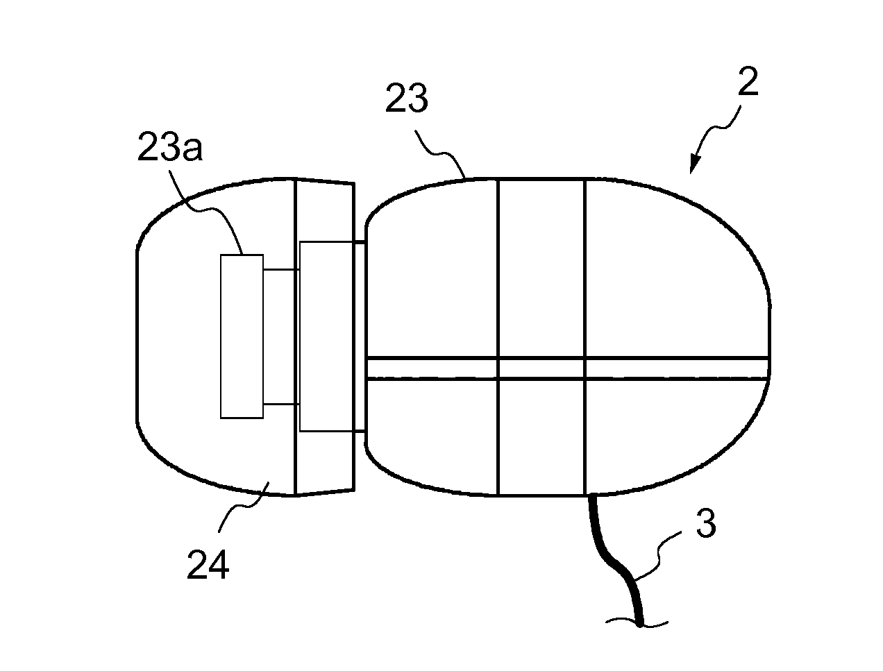
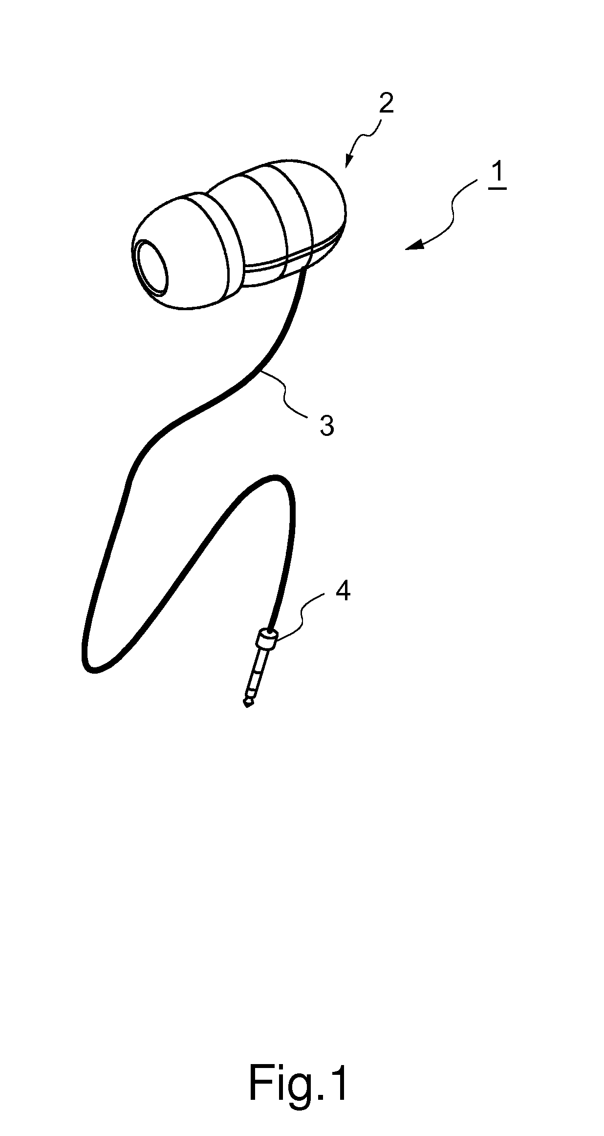
[0026]FIG. 1 is an external perspective view of an earphone microphone according to a first embodiment. An earphone microphone 1 is a sound input and output device that is connected to electronic equipment (not shown) such as a cellular phone, for example. As illustrated in FIG. 1, the earphone microphone 1 includes a main body 2, a cable 3, and a connector 4.

[0027]The main body 2 is placed in a user's ear so as to produce output sound and to pick up input sound from an external sound source (such as user's speaking voice). A specific structure of the main body 2 will be described later. The cable 3 is a signal wire connected between the main body 2 and the connector 4 so as to transmit and receive signals between electronic equipment (not shown) connected to the earphone microphone 1 and the main body 2 via the connector 4. The connector 4 is an input and output terminal connected to an interface of the electronic equipment (not shown).

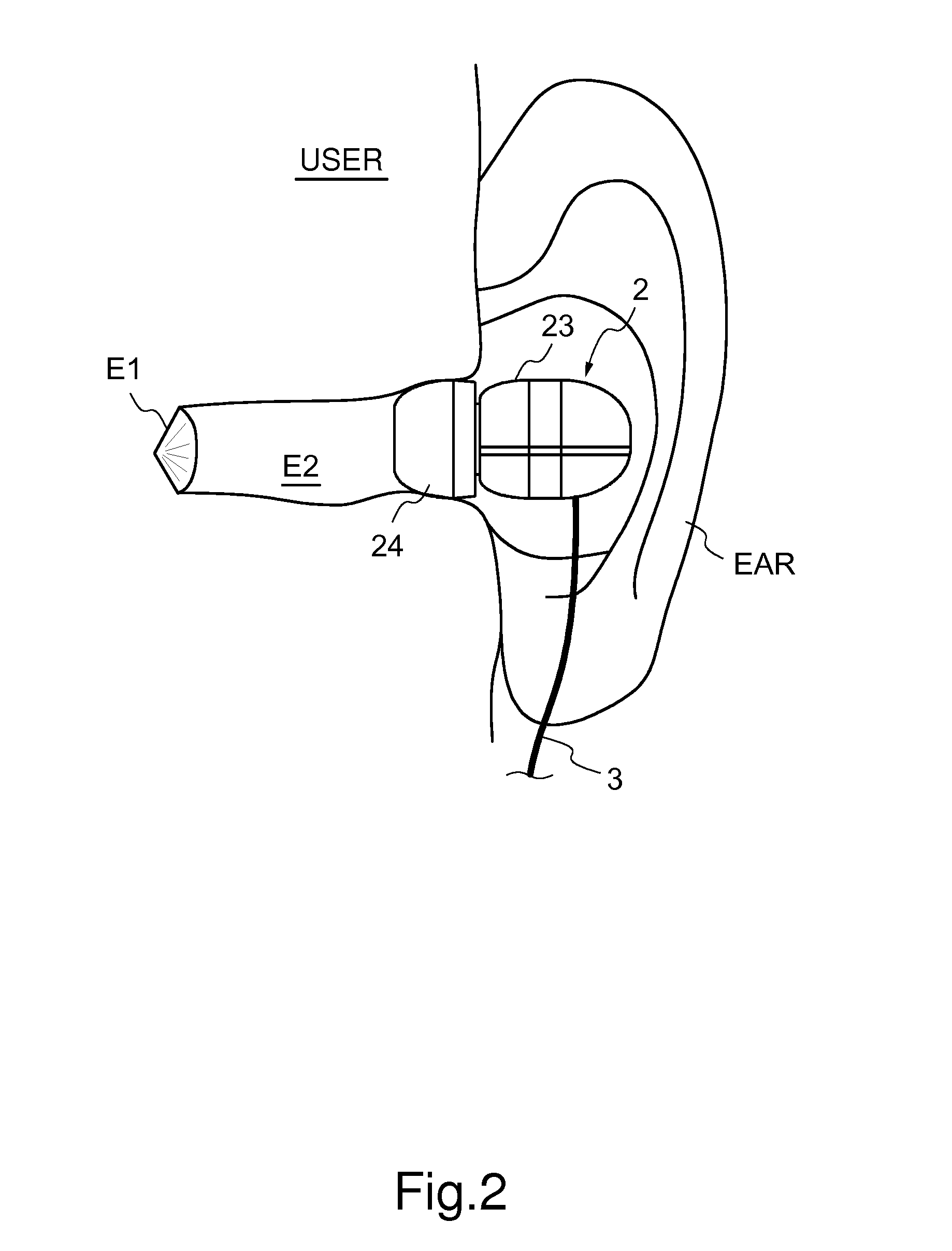
[0028]FIG. 2 is a diagram illustrating a state...

second embodiment

[0050]Next, the earphone microphone 1 of the second embodiment is described. In the second embodiment, a root of the cable 3 is covered with a sheath member 3a. In addition, the second opening 232 is communicated with the outside of the main body case 23 through a gap between the sheath member 3a and the cable 3. Other than that is the same as the first embodiment. In the following description, the same structural element as the first embodiment is denoted by the same numeral or symbol, and description thereof is omitted.

[0051]FIG. 8 is a schematic cross-sectional view of the main body of the earphone microphone placed in the user's ear according to the second embodiment. In FIG. 8, the propagation path of the input sound propagating to the microphone 22 via the tympanum E1 and the external acoustic meatus E2 is illustrated by a solid line. In addition, the propagation path of the external sound (so-called noise) propagating from the outside of the main body case 23 other than the e...

third embodiment

[0056]Next, the earphone microphone 1 according to a third embodiment is described. In the third embodiment, the sound output passage 233a and the sound input passage 233b make the same acoustic space 233. Other than that is the same as the first and second embodiments. In the following description, the same structural element as the first and second embodiments is denoted by the same numeral or symbol, and description thereof is omitted.

[0057]FIG. 9 is a schematic cross-sectional view of a main body of the earphone microphone placed in the user's ear according to the third embodiment. In FIG. 9, the propagation path of the input sound propagating to the microphone 22 through the tympanum E1 and the external acoustic meatus E2 is illustrated by a solid line. In addition, the propagation path of the external sound (so-called noise) propagating from the outside of the main body case 23 other than the external acoustic meatus E2 to the microphone 22 is illustrated by a broken line. In ...


PUM


Abstract

Provided is an earphone microphone capable of outputting sound with good quality and picking up clear sound. The earphone microphone includes a speaker, a microphone, a main body case, and a seal member. The seal member seals between the main body case and user's external acoustic meatus when the earphone microphone is inserted in the external acoustic meatus. The main body case is provided with an acoustic space in which the speaker and the microphone are disposed, and a first opening and a second opening which are communicated with the acoustic space. When the earphone microphone is inserted in the external acoustic meatus, the first opening is communicated with the external acoustic meatus while the second opening is communicated with outside of the main body case other than the external acoustic meatus.

Description

[0001]This application is based on Japanese Patent Application No. 2013-151664 filed on Jul. 22, 2013, contents of which are hereby incorporated by reference.BACKGROUND OF THE INVENTION[0002]1. Field of the Invention[0003]The present invention relates to an earphone microphone and particularly to an earphone microphone including a speaker and a microphone.[0004]2. Description of Related Art[0005]Conventionally, there is known an earphone microphone including a speaker and a microphone. A user who puts on the earphone microphone can transmit his or her voice input to the microphone while hearing sound such as speaking voice output from the speaker. Therefore, the earphone microphone is used for handsfree communication with a cellular phone or the like.[0006]In general, a canal type of the earphone microphone such as described in JP-A-2007-201887 is often used. When a user puts on a canal type earphone microphone placed in an ear, the external acoustic meatus of the user is sealed by ...

Claims


Application Information

Patent Timeline
Patent Type & Authority Applications(United States)
IPC IPC(8): H04R1/08H04R1/10
CPCH04R1/08H04R1/1058H04R1/1075H04R1/1016H04R1/1083H04R1/222H04R2201/107H04R2410/01
Inventor SHIMIZU, NORIYUKI
Owner FUNAI ELECTRIC CO LTD
Why Eureka
Try Eureka