Low Vibration Fan

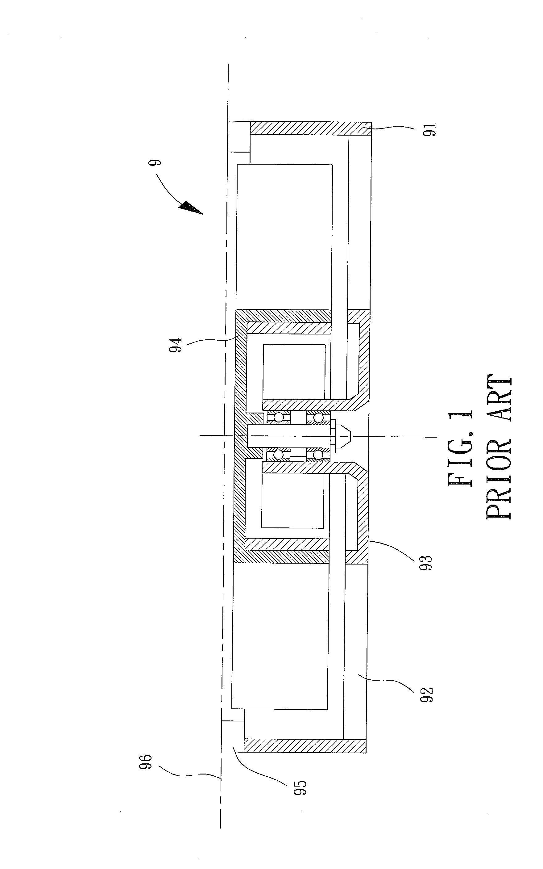
a fan and low-vibration technology, applied in the field of fans, can solve the problems of shortening the lowering the operational stability of the electronic system, and reducing the vibration-damping performance of the rubber column b>95/b>, so as to prolong the service life of the electronic system and reduce nois

Inactive Publication Date: 2015-01-22
SUNONWEALTH ELECTRIC MACHINE IND
View PDF10 Cites 9 Cited by
  • Summary
  • Abstract
  • Description
  • Claims
  • Application Information

AI Technical Summary

Benefits of technology

[0018]When the low vibration fan is installed in an electronic system, based on the feature that the maximal outer diameter of the base is not larger than the minimal inner diameter of the outer frame (preferably including the radial buffer gap formed between the outer frame and the base), the vibration that is caused during the operation of the impeller and is transferred from the base to the outer frame can be significantly reduced. As a result, the noise is reduced and the service life of the electronic system is prolonged.

Problems solved by technology

However, since there is vibration in the rotation of the fan wheel usually, said vibration can easily transmit to the casing of the electronic system via the frame.
This kind of vibration not only induces noises, but also lowers the operational stability of the electronic system as well as accelerates the deterioration of the circuit joints inside the electronic system, and thus shortens the lifetime of this electronic system.
However, the vibration-damping performance of the rubber column 95 is quite limited, and thus the housing 96 still suffers the vibration caused by the operated impeller 94 since said vibration is continuously transmitted to the frame 91 via a route formed by the ribs 92 due to the rotatable coupling between the impeller 94 and the base 93.
Therefore, the remaining vibration can still lower the operational stability of the electronic system, induce noises, and shorten the lifetime of this electronic system when the conventional fan 9 is installed in this electronic system and operated.
Moreover, the said remaining vibration may also cause a fault or failure in reading operation of a hard disk in the electronic system.

Method used


Image

  • Low Vibration Fan
  • Low Vibration Fan
  • Low Vibration Fan

Examples


Embodiment Construction

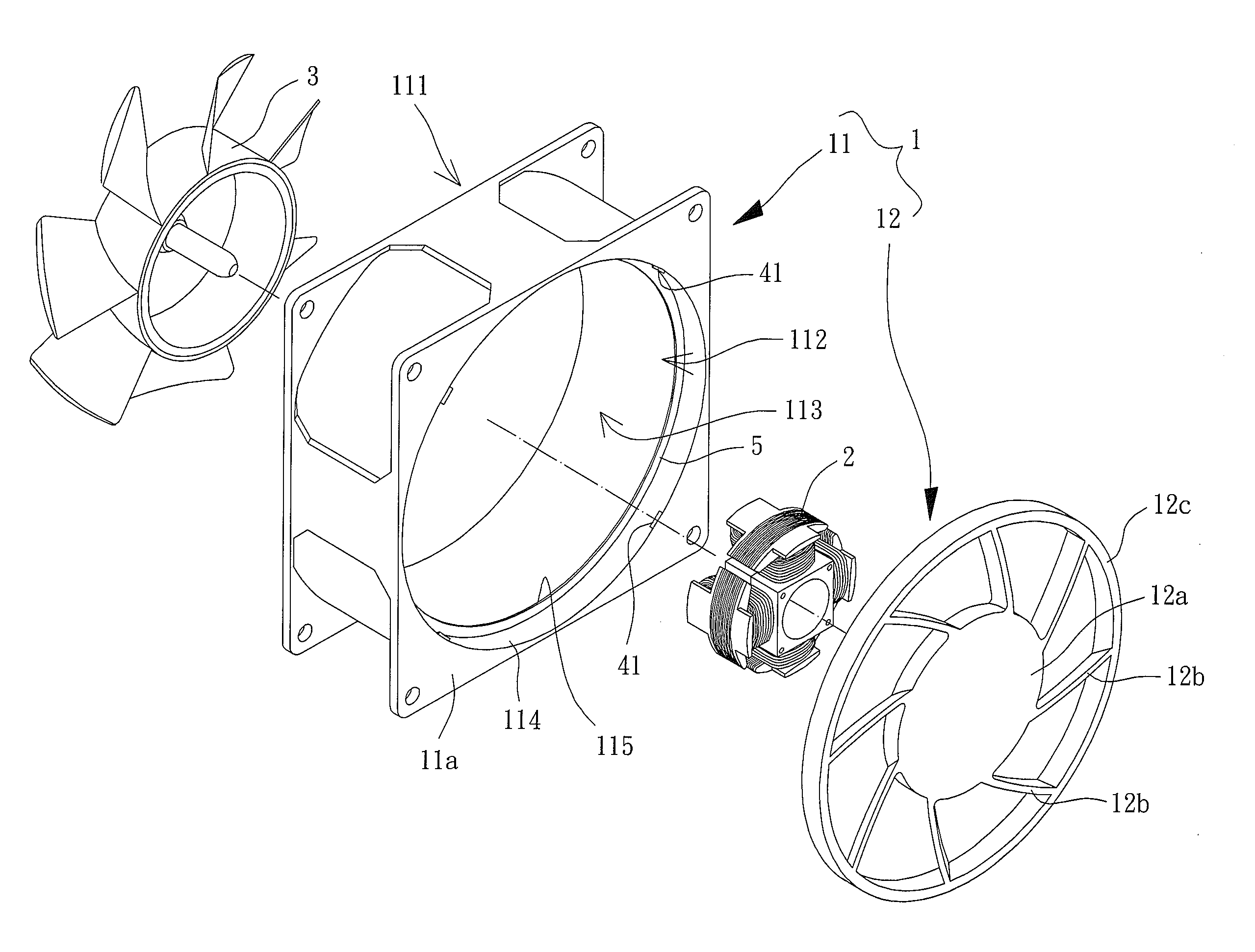
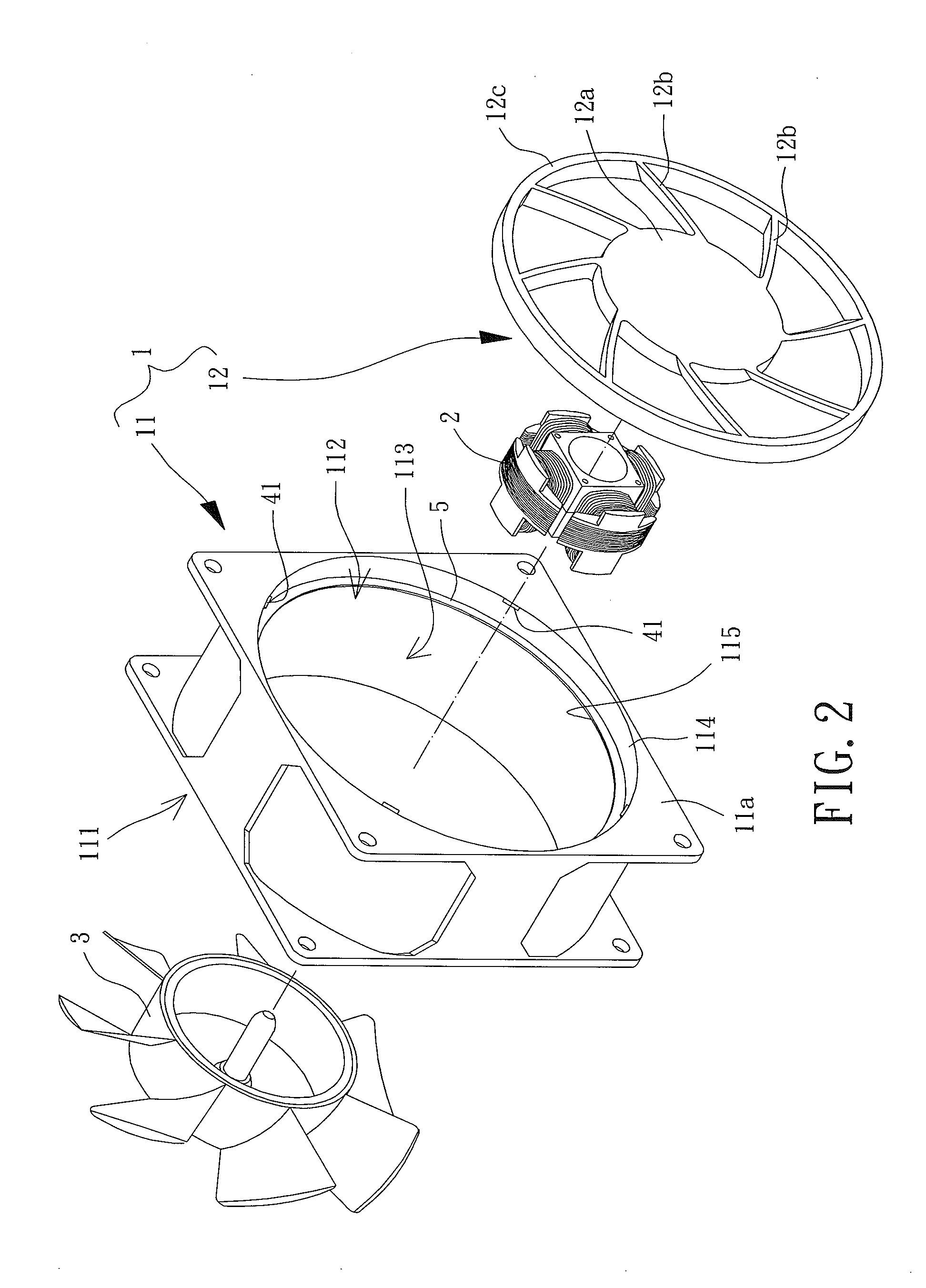
[0036]Referring to FIGS. 2 and 3, a first embodiment of a low vibration fan of the present invention is shown, which includes a housing 1, a driving member 2 and a fan wheel 3. The housing 1 is in a structure for guiding air flows to enter and exit said low vibration fan, such as a housing structure of an axial fan, a centrifugal fan, or an advection fan (which guides air current to flow in and out of the fan in a radial direction), which is shown as that of an axial fan for example in the following illustration.

[0037]The driving member 2 is coupled inside the housing 1. The fan wheel 3 is rotatably mounted on the driving member 2 so as to be turned by the driving member 2. Specifically, a shape of the housing 1 is not limited as long as this shape is capable of receiving the driving member 2 as well as the fan wheel 3. For instance, the housing 1 can be a polygonal shape, a circular shape or an elliptic shape. In the following embodiments, the housing 1 is in a rectangular shape.

[0...


PUM


Abstract

A low vibration fan including a housing, a driving member and a fan wheel is provided. The housing has an outer frame and a base, wherein the outer frame has two openings, a positioning rim, and a guiding channel linking the two openings, wherein the base couples with the positioning rim, and wherein a radial buffer gap is formed between an outer periphery of the base and an inner periphery of the positioning rim. The driving member is mounted on the base. The fan wheel couples with the driving member rotatably. Accordingly, the radial buffer gap can largely reduce the vibration transmitted from the base to the outer frame.

Description

BACKGROUND OF THE INVENTION[0001]1. Field of the Invention[0002]The present invention generally relates to a fan and, more particularly, it relates to a low vibration fan.[0003]2. Description of the Related Art[0004]A conventional fan usually includes a frame receiving a rotatable fan wheel inside. When the conventional fan is received inside an electronic system, an air current induced by the rotation of the fan wheel can provide a desirable cooling effect to electronic elements of the electronic system.[0005]However, since there is vibration in the rotation of the fan wheel usually, said vibration can easily transmit to the casing of the electronic system via the frame. This kind of vibration not only induces noises, but also lowers the operational stability of the electronic system as well as accelerates the deterioration of the circuit joints inside the electronic system, and thus shortens the lifetime of this electronic system.[0006]Therefore, referring to FIG. 1, an invention ...

Claims


Application Information

Patent Timeline
Patent Type & Authority Applications(United States)
IPC IPC(8): F04D29/66
CPCF04D29/668F04D25/0613F04D19/002F04D29/646
Inventor LI, MING-TSUNGCHANG, FENG-MINGHU, WAN-LING
Owner SUNONWEALTH ELECTRIC MACHINE IND
Why Eureka
Try Eureka