Method and device for repolarizing a piezoelectric actuator of an injector of an internal combustion engine of a used vehicle

a piezoelectric actuator and injector technology, which is applied in the direction of electric control, machines/engines, mechanical apparatus, etc., can solve the problems of low engine speed and therefore low nominal voltage, change in the polarization of the piezoelectric actuator, and less precise control

Active Publication Date: 2015-01-29
VITESCO TECH GERMANY GMBH
View PDF3 Cites 3 Cited by
  • Summary
  • Abstract
  • Description
  • Claims
  • Application Information

AI Technical Summary

Benefits of technology

[0004]In order to be stable and have reproducible behaviour, a piezoelectric actuator must be polarized at a reference value, this being done in the factory during the manufacture of said actuator, and before the engine is put into use in a vehicle. This polarization, called the initial polarization, consists in applying an electrical charge by means of a specified voltage, called the polarization voltage, for a period which is also specified, across the terminals of the piezoelectric actuator, thereby causing the crystal structure of the latter to be orientated in the direction of the electric field established in the piezoelectric stack, corresponding to the direction in which the variation of the dimension of the piezoelectric actuator is desired. After the removal of this initial polarization voltage at the terminals of the piezoelectric stack, this stack retains a residual polarization state for its subsequent use.

Problems solved by technology

However, a piezoelectric actuator tends to lose this initial polarization during its use in an internal combustion engine, notably because of the essentially urban use of the vehicle, resulting in low engine speeds and therefore low nominal voltages, considerably below the polarization voltage, for operating the injectors under low fuel pressure.
Other conditions of use, such as repeated cycles of increase and / or decrease in the engine temperature, or long periods without the use of the piezoelectric actuator, corresponding to prolonged periods of immobilization of the vehicle, may also lead to a change in the polarization of the piezoelectric actuator over time.
The increase in this clearance results in less precise control of the actuator, which may even lead to the loss of one or more injections of small amounts of fuel, for example what are known as pilot injections, since the injector no longer has time to compensate for the clearance and open the valve for brief time intervals, causing increased engine noise (the main injection combustion takes place with a high pressure gradient owing to the lack of a pilot injection) and pollution, as well as making driving disagreeable.
For longer periods of opening of the injector, the drift of the piezoelectric actuator leads to poor control of the amount of fuel actually injected into the combustion chamber.
Furthermore, it is no longer possible to perform a new initial polarization on a previously polarized piezoelectric actuator, since the actuator undergoes processing after the initial polarization in which it is covered with an insulating protective coating and mounted in the injector housing.
This it is no longer possible to perform this initial polarization procedure which, in most cases, requires the application of stresses to the stack of piezoelectric ceramic layers and a high temperature of more than 100° C.
However, there are methods of compensating for the depolarization of a piezoelectric actuator with the aim of polarizing the actuator again after the initial polarization applied when the product left the factory, these methods being more or less effective and costly, and generally requiring the dismounting of the injector.
In many cases, the piezoelectric actuator, or even the whole injector, is replaced when the depolarization is too great and can no longer be compensated effectively.

Method used


Image

  • Method and device for repolarizing a piezoelectric actuator of an injector of an internal combustion engine of a used vehicle
  • Method and device for repolarizing a piezoelectric actuator of an injector of an internal combustion engine of a used vehicle
  • Method and device for repolarizing a piezoelectric actuator of an injector of an internal combustion engine of a used vehicle

Examples


Embodiment Construction

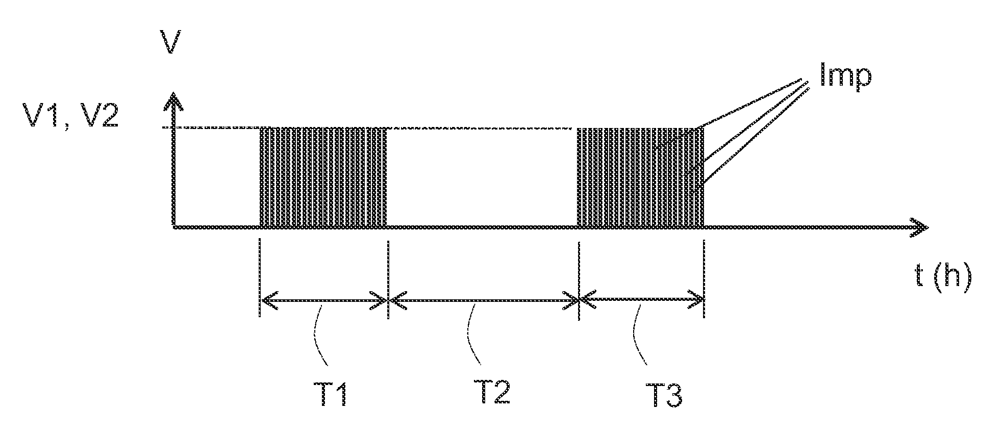
[0042]The repolarization method shown in FIGS. 1 to 3 is applied to a piezoelectric actuator of an injector of an internal combustion engine of a used vehicle (not shown), the piezoelectric actuator having undergone initial polarization before the vehicle was put into use. During the application of the method as described, the piezoelectric actuator is associated with the injector, according to the original mounting, the injector being mounted on the engine, and the engine being stopped. The injector is therefore in its original mounting on the vehicle. The method as described does not require the dismounting of the actuator or the injector. It can advantageously be used in a service station during the servicing of the vehicle.

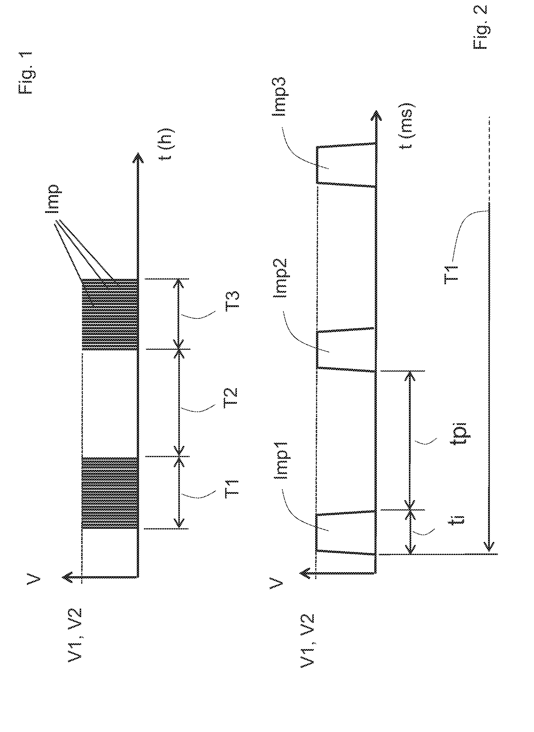
[0043]In FIGS. 1 and 2, the time t for the execution of the method as described is shown on the horizontal axis, while the voltage V applied to the terminals of the piezoelectric actuator is shown on the vertical axis.

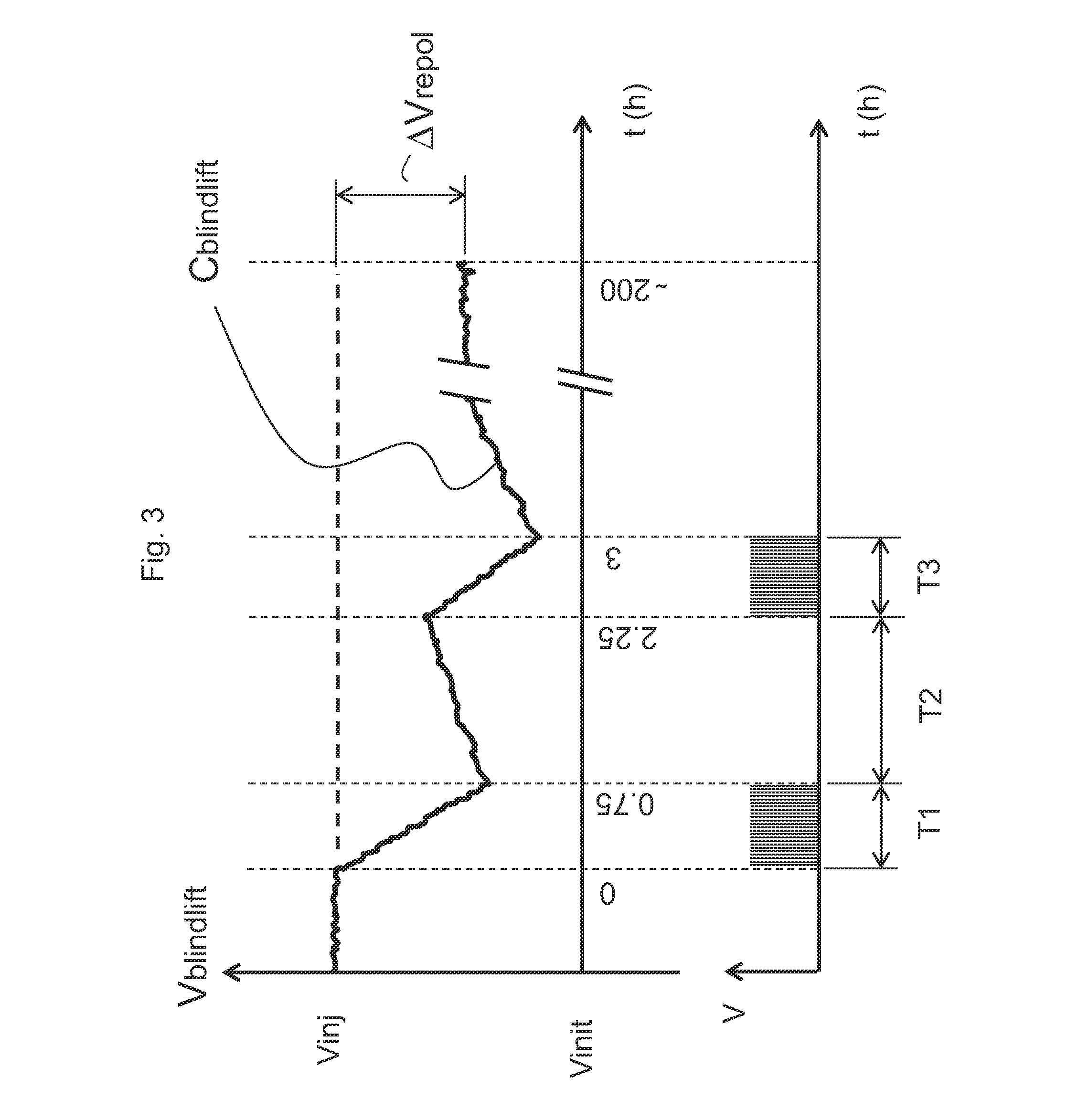
[0044]The method according to FIGS. 1 to 3...


PUM

PropertyMeasurementUnit
polarization voltageaaaaaaaaaa
temperatureaaaaaaaaaa
timeaaaaaaaaaa

Abstract

A method for repolarizing a piezoelectric actuator associated with an injector mounted on an internal combustion engine of a vehicle, the piezoelectric actuator having undergone initial polarization before the vehicle was used, includes with the engine stopped:
    • applying a first polarization voltage to the terminals of the piezoelectric actuator during a first specified time interval of not less than ten minutes,
    • stopping the application of the first polarization voltage during a second time interval, following the first time interval and at least equal to the latter,
    • applying a second polarization voltage to the terminals of the piezoelectric actuator during a third specified time interval, following the second time interval,
    • stopping the application of the second polarization voltage to the terminals of the piezoelectric actuator after the third time interval,
the successive first, second and third time intervals defining a repolarization sequence of the piezoelectric actuator.

Description

FIELD OF THE INVENTION[0001]The present invention relates to a method and a device for repolarizing a piezoelectric actuator of an injector of an internal combustion engine of a used vehicle, said piezoelectric actuator having undergone initial polarization before the vehicle was put into use.BACKGROUND OF THE INVENTION[0002]There is a known way of using a piezoelectric actuator to control the opening and closing of an injector in an internal combustion engine running on a fuel such as petrol or diesel oil.[0003]A piezoelectric actuator is mainly composed, in a known way, of a stack of ceramic elements defining a specified length, which has the property of having its length modified by the action of an electric field, and, conversely, of producing an electric field under the action of a mechanical stress; this stack is placed in an injector between a stop and the valve means, and operates, in summary, in the following manner: when an electrical charge is applied, by means of a volta...

Claims


Application Information

Patent Timeline
Patent Type & Authority Applications(United States)
IPC IPC(8): F02M51/06
CPCF02M51/0603F02D41/2096F02D2200/0602Y10T29/42H10N30/045
Inventor LEBLON, MICHAELATANASYAN, ALAINAGNUS, YVES
Owner VITESCO TECH GERMANY GMBH
Why Eureka
Try Eureka