Flame monitoring of a gas turbine combustor using a characteristic spectral pattern from a dynamic pressure sensor in the combustor
- Summary
- Abstract
- Description
- Claims
- Application Information
AI Technical Summary
Benefits of technology
Problems solved by technology
Method used
Image

Examples
Embodiment Construction
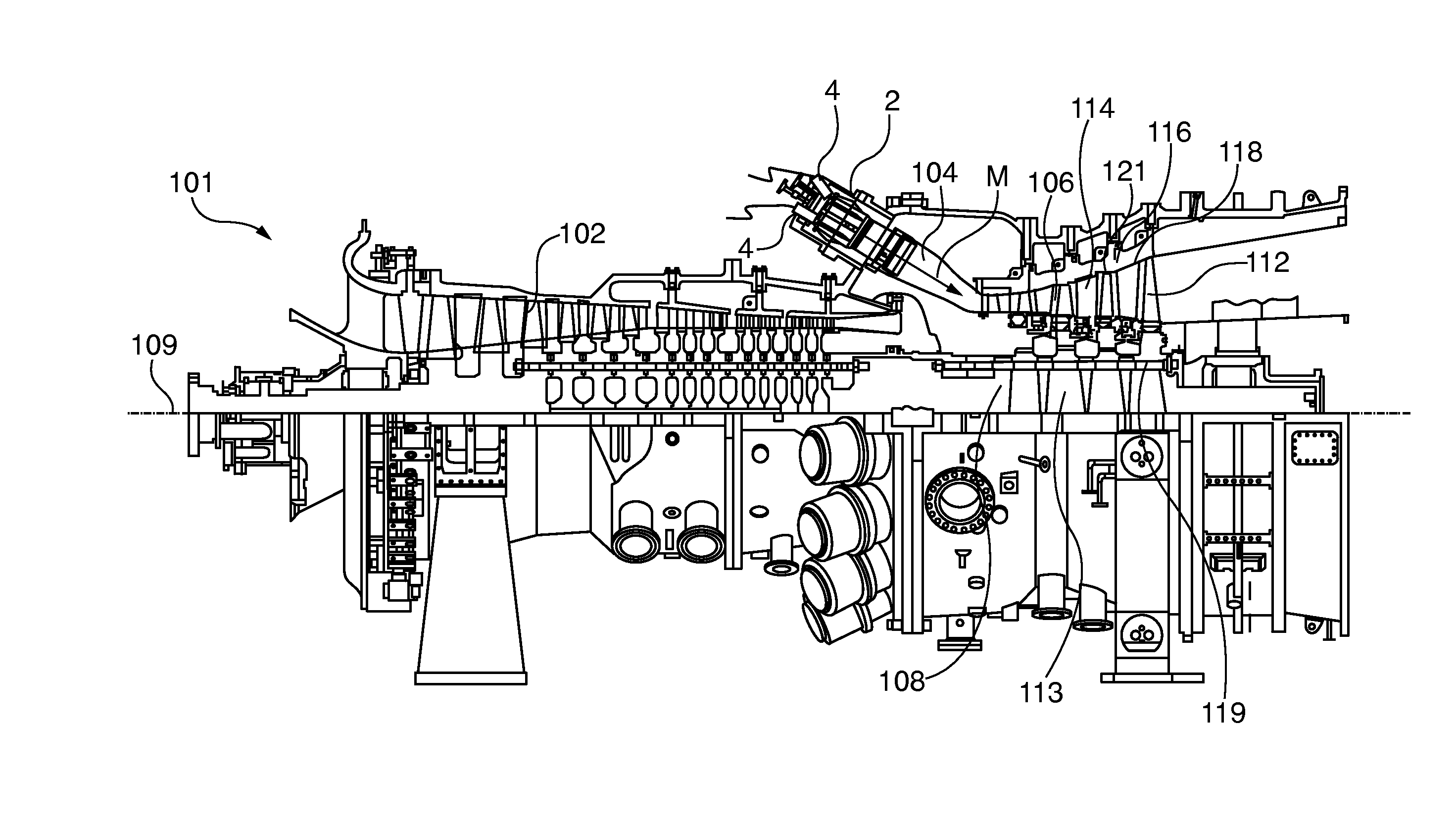
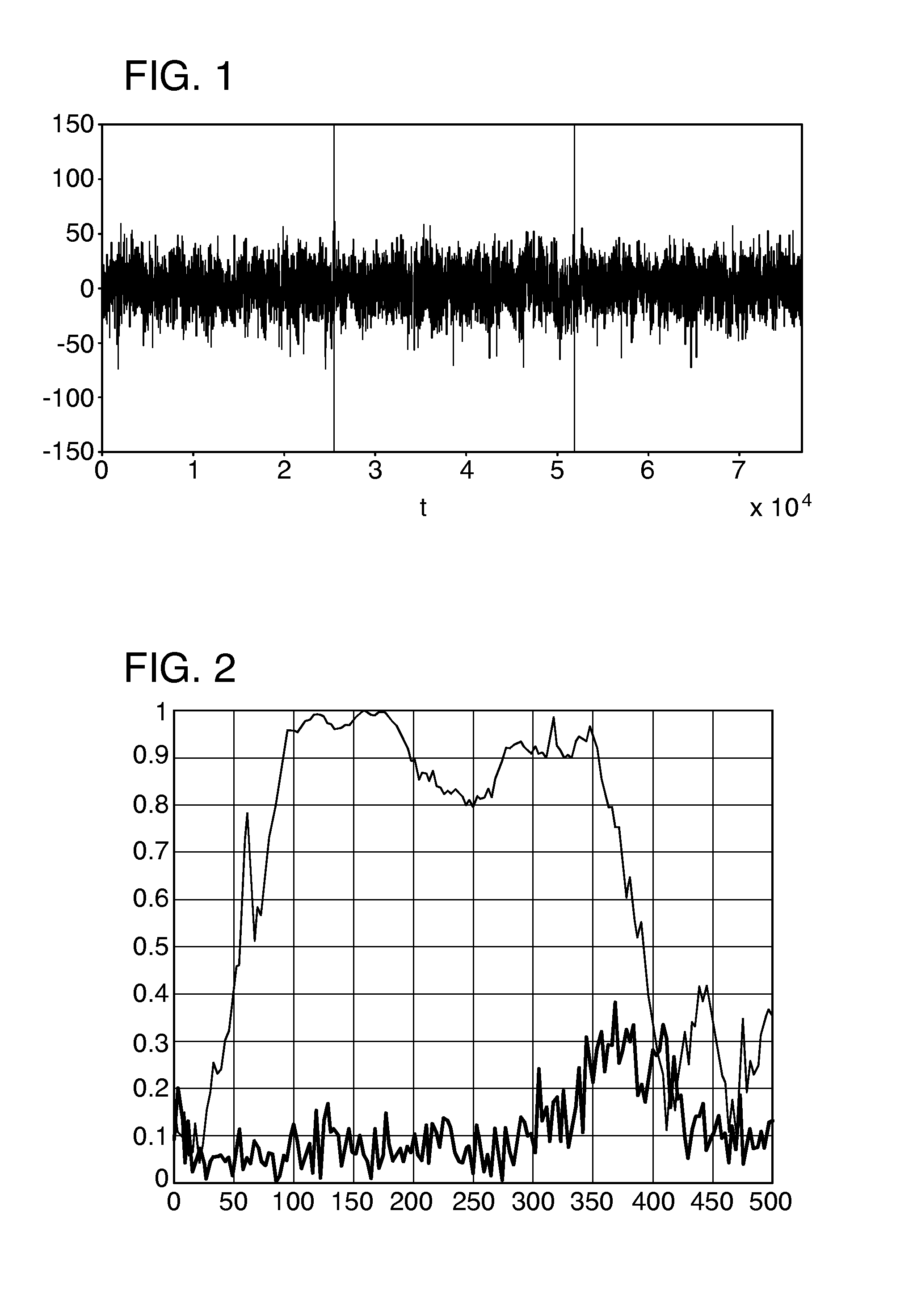
[0059]FIG. 1 shows the signals of two dynamic pressure sensors which are based on piezoelectricity in order to provide an optimal, precise pressure measurement. Alternatively, sensors of a different type may be used as pressure sensors provided they permit the current pressure value to be inferred, for example thermocouple elements whose signal also has a dependent relationship with the pressure signal. The dynamic pressure sensors are arranged at two different locations in the pressure influence zone of a combustor in a gas turbine. What is understood by pressure influence zone in this context is an area whose pressure fluctuations are dependent to a large extent on the dynamics of the flame of the respective combustor. In the case of a gas turbine of the can-annular type this can be for example an area within the respective basket of the combustor. The pressure sensors are typically arranged upstream of the flame. The gas turbine is explained in detail below with reference to FIG....
PUM
 Abstract
Description
Claims
Application Information
 - Generate Ideas
- Intellectual Property
- Life Sciences
- Materials
- Tech Scout
- Unparalleled Data Quality
- Higher Quality Content
- 60% Fewer Hallucinations
Browse by: Latest US Patents, China's latest patents, Technical Efficacy Thesaurus, Application Domain, Technology Topic, Popular Technical Reports.
© 2025 PatSnap. All rights reserved.Legal|Privacy policy|Modern Slavery Act Transparency Statement|Sitemap|About US| Contact US: help@patsnap.com