
Carbon Nanotube Composite Membrane

a carbon nanotube and composite membrane technology, applied in the direction of membranes, liquid degasification, separation processes, etc., can solve the problems of reducing the strength and durability of the membrane, affecting the performance of the primary selective membrane, and reducing the strength of the membrane, so as to achieve the effect of reducing the cost of the separation membrane, enhancing the strength properties of the membrane, and reducing the thickness of the membran

Active Publication Date: 2015-01-29
IDEX HEALTH & SCI
View PDF13 Cites 5 Cited by
  • Summary
  • Abstract
  • Description
  • Claims
  • Application Information

AI Technical Summary

Benefits of technology

The present invention is about a way to make thin membranes for separations using less polymer material while maintaining strength. This is done by using a reinforcement structure made of randomly oriented carbon nanotubes. This structure helps reduce the effective film thickness of the polymer, resulting in cost savings. The carbon nanotubes are integrated into the polymer, allowing for better gas permeability.

Problems solved by technology

As a result, a thinner membrane is typically desired, but is limited by the decreased strength and durability as membrane thickness is reduced.
It is therefore an ongoing challenge to obtain selective membranes that have the highest possible permeance without being unduly fragile.
A variety of reinforcing support structures have been previously implemented, but are typically difficult to handle, expensive, and / or degrade the performance of the primary selective membrane.
The particular method of forming nanotubes into such sheets, tapes, and the like, however, can greatly affect the strength of the so-formed macro-scale nanotube structures.
Generally, the bonding interactions among the nanotubes are insufficient to form a buckypaper that has commercial use on its own.
In some cases, surface energy matching is not possible without chemical modification of the reinforcing material, which chemical modification can be expensive or even impossible.
One explanation for the lack of work in this area may be due to the expectation that carbon nanotube fabrics would act similarly to other reinforcement structures that interfere with the overall permeability of the composite structure.
It is well know that solid portions of conventional thin film support structures often reduce permeance performance as compared to the neat thin film separation membrane.

Method used


Image

  • Carbon Nanotube Composite Membrane
  • Carbon Nanotube Composite Membrane
  • Carbon Nanotube Composite Membrane

Examples


example 1

[0044]The composite membrane of Case 1 from Table 4 was prepared by dip coating the carbon nanotube fabric in the polymer solution for 72 hours while stretched over an aluminum frame. Following submersion for 72 hours, the composite material was withdrawn from solution and held in an atmosphere saturated with FC-770 solvent to prevent drying of the composite, and the excess solution was allowed to drain from the surface of the wet composite. The composite was then allowed to dry under ambient conditions under sufficient tension to remove wrinkles.

[0045]The dried composite membrane was then laser cut into one inch by two inch samples for tensile strength measurements, permeability and permeance testing, and scanning electron microscopy. The following Table 5 sets forth testing results of the composite membrane, in comparison to neat polymer films formed from Teflon® AF-2400 through extrusion, solution casting, melt pressing, and laboratory bench casting.

TABLE 5Permeability,PermeanceT...

example 2

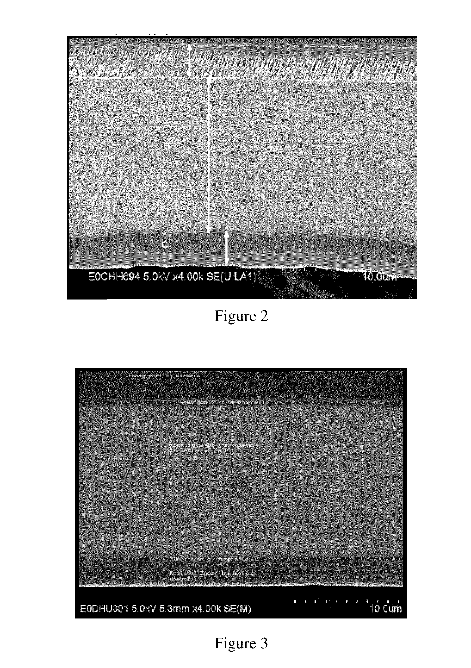
[0058]The composite membrane described in Case 2 of Table 4 was prepared by soaking the carbon nanotube fabric in solution for 72 hours. Following soak, the composite was pressed while in the presence of polymer solution, and subsequently placed on a glass surface. Excess polymer solution was removed from the composite using a squeegee while compressing the composite surface to ensure the polymer solution beneath the composite against the glass was minimized and to remove air bubbles regained between the glass surface and the composite membrane. The composite membrane was then dried at ambient, followed by oven drying at 60° C. for four hours.

[0059]The following table sets forth strength, permeability, and permeance results for the composite membrane:

TABLE 7PermeabilityPermeance,ThicknessTensile(Barrer)(GPU) (1.1 cm dia)O2 / N2Type(Microns)(GPa)O2N2CO2O2N2CO2ratioExtruded381.7 58527315001.6.754.172.14Cast19n / a882446208046.623.51091.97Composite135.9617409004590134703531.93Membrane(Tabl...

example 3

[0063]A composite membrane in accordance with Case 3 of Table 4 was prepared using the procedure of Example 2. The tensile strength of the composite membrane was compared to a membrane cast from Solution 5 of Table 3:

TABLE 9TensileStrengthMembrane(GPa)NotesPolymer only0.99Pure polymer(Table 3, Type 5)Composite Membrane6.95Hyflon AD-60 composite with(Table 4, Case 3)10 gram / m2 Nanocomp fabric


PUM

PropertyMeasurementUnit
tensile strengthaaaaaaaaaa
lengthaaaaaaaaaa
diameteraaaaaaaaaa

Abstract

A composite membrane for separations includes a fabric with a non-woven array of intermingled carbon nanotubes, and a dopant incorporated with the fabric to form a non-porous, permeable composite. The composite membrane may be used to separate a target gas from a liquid by mounting the composite membrane in a housing chamber, and conditioning a permeate side of the chamber to establish a driving force for the target gas across the non-porous, permeable composite membrane.

Description

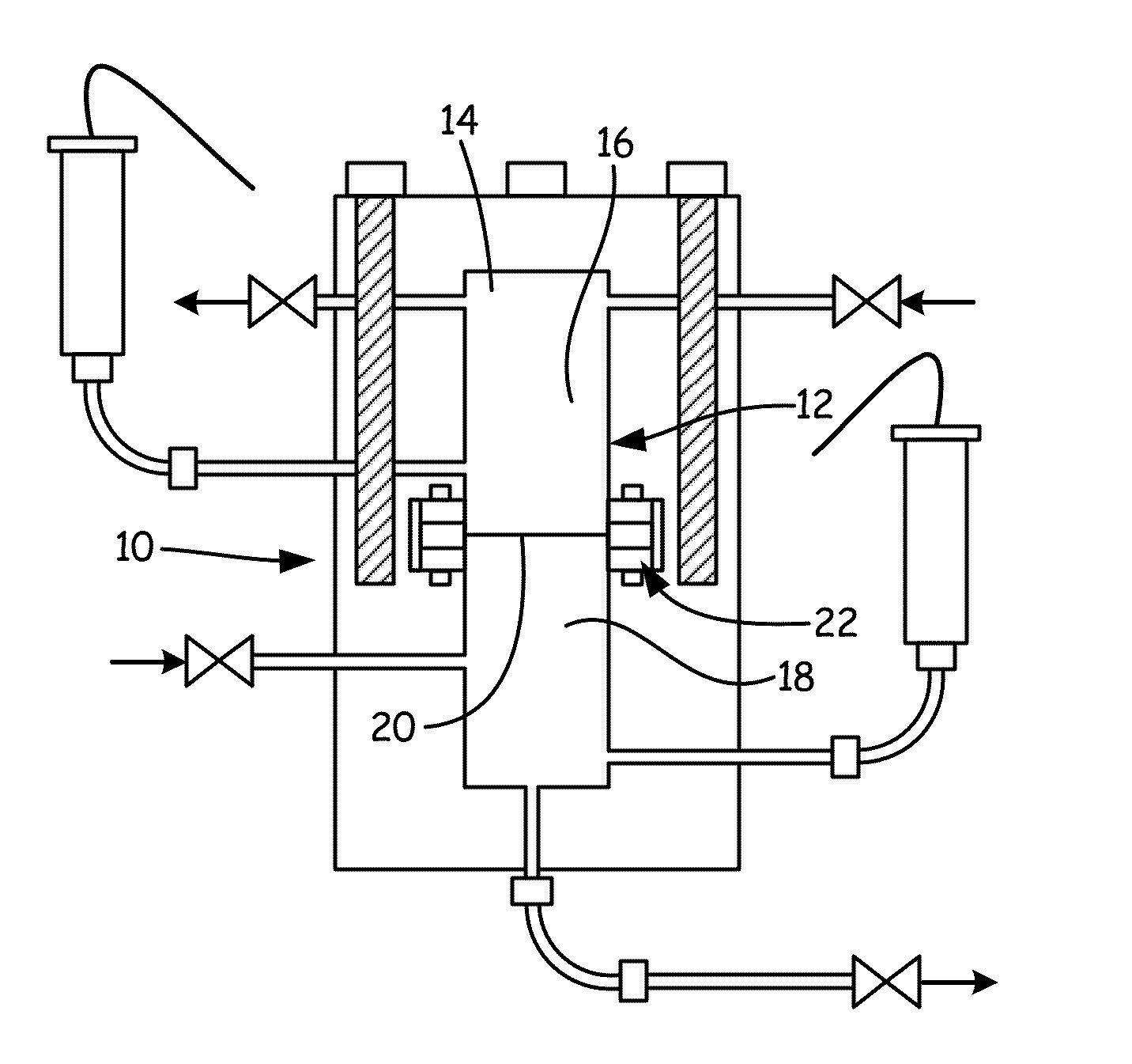
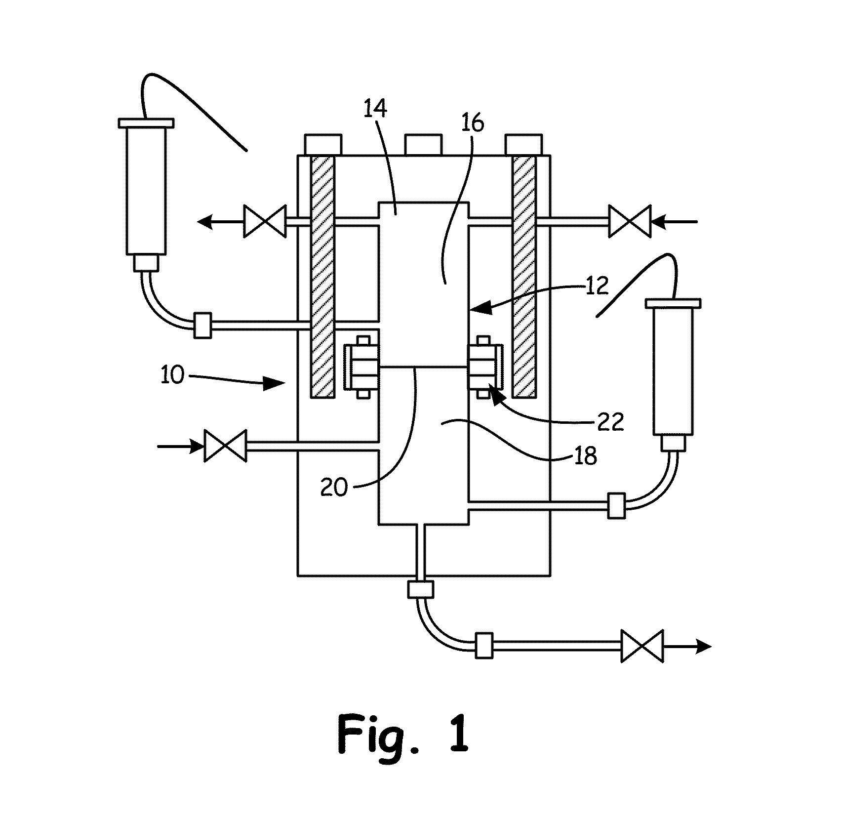
FIELD OF THE INVENTION[0001]The present invention relates to gas separation and ion transport membranes generally, and more particularly to a composite membrane structure having a backbone of an array of nanotubes.BACKGROUND OF THE INVENTION[0002]A long list of polymers have been studied in the past for their utility in the formation of membranes for a variety of purposes. Of importance to the present invention is the use of such polymer membranes for separations and selective transport to modify a feed material and / or to recover one or more target species from the feed material. A host of polymers have been determined to be useful for such applications, with each material exhibiting its own benefits and drawbacks for particular membrane separation and transport applications.[0003]An application of particular interest to the Applicant is the degassing of liquids through contact with a gas-permeable, liquid-impermeable membrane. Such liquid-gas contactors typically rely upon Henry's ...

Claims


Application Information

Patent Timeline
Patent Type & Authority Applications(United States)
IPC IPC(8): B01D19/00
CPCB01D19/0031B01D53/228B01D69/02B01D69/148B01D71/32B01D2325/14B01D2325/24B01D69/107B01D71/0212
Inventor SIMS, CARL W.LIU, QUAN
Owner IDEX HEALTH & SCI
Learn More