Fuel cell vehicle
- Summary
- Abstract
- Description
- Claims
- Application Information
AI Technical Summary
Benefits of technology
Problems solved by technology
Method used
Image

Examples
first embodiment
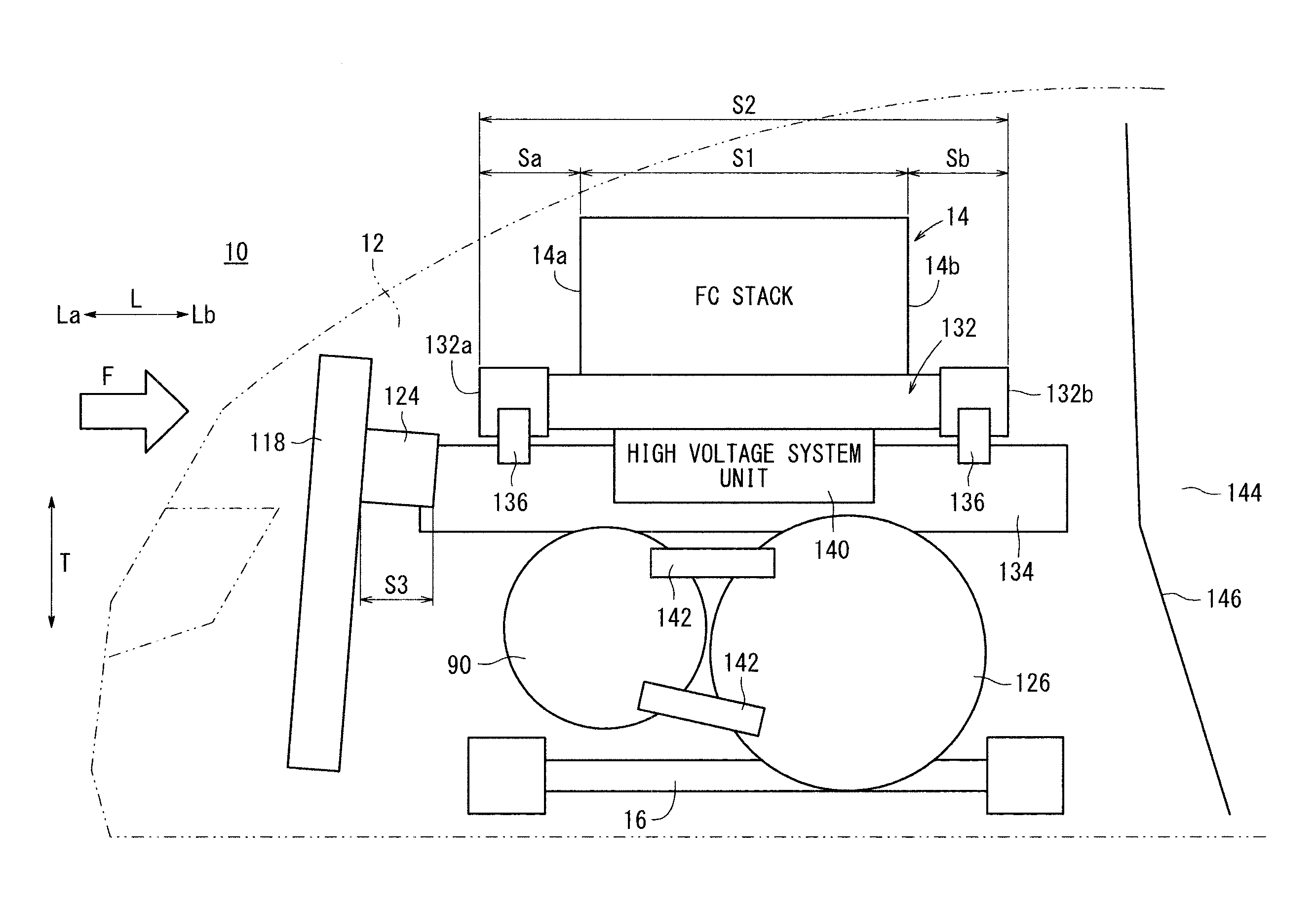
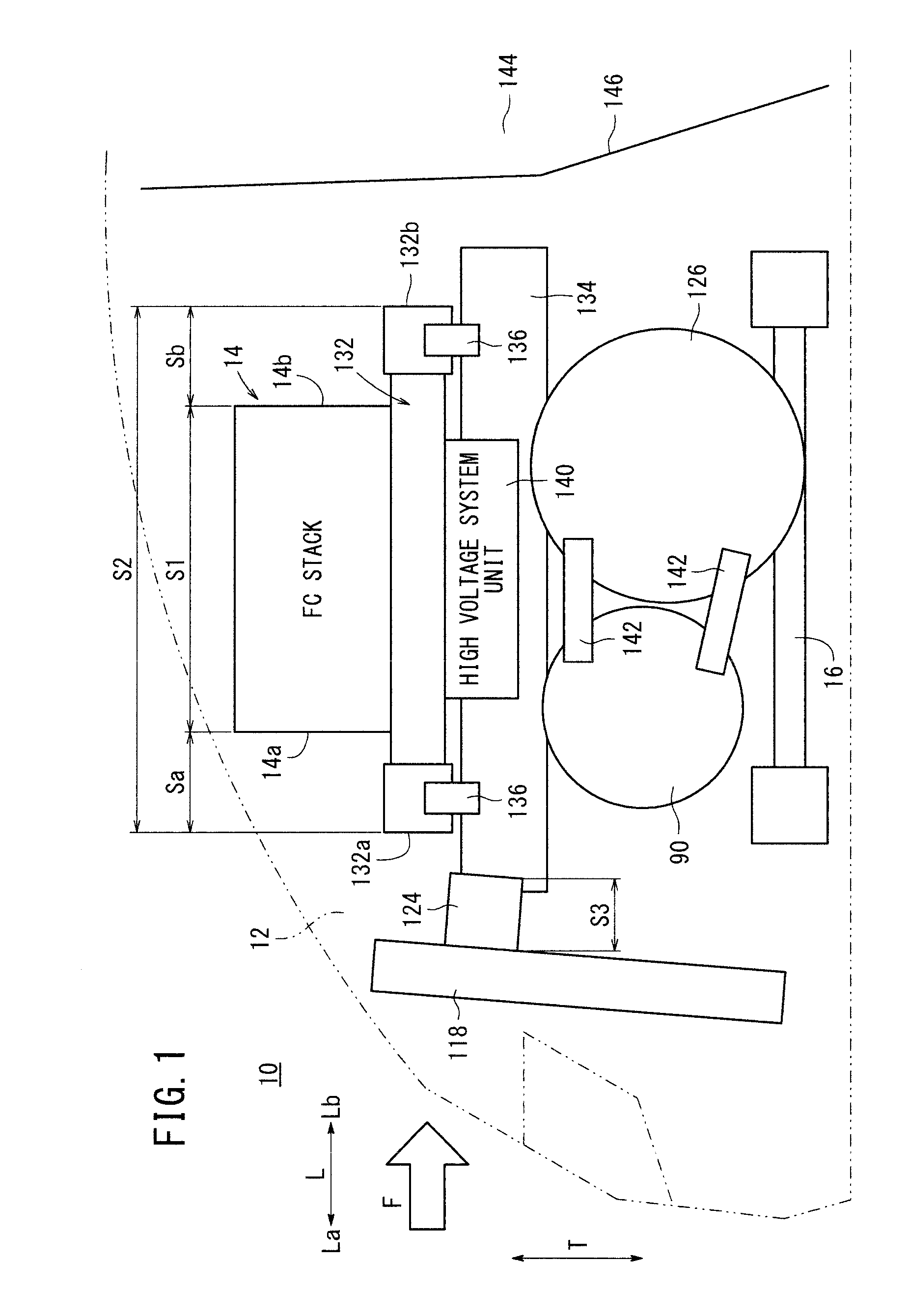
[0025]As shown in FIGS. 1 to 3, a fuel cell vehicle 10 according to the present invention includes a fuel cell stack 14 placed in a front box (so called motor room) 12, and a vehicle body frame (vehicle frame) 16 for mounting the fuel cell stack 14 in the front box 12.
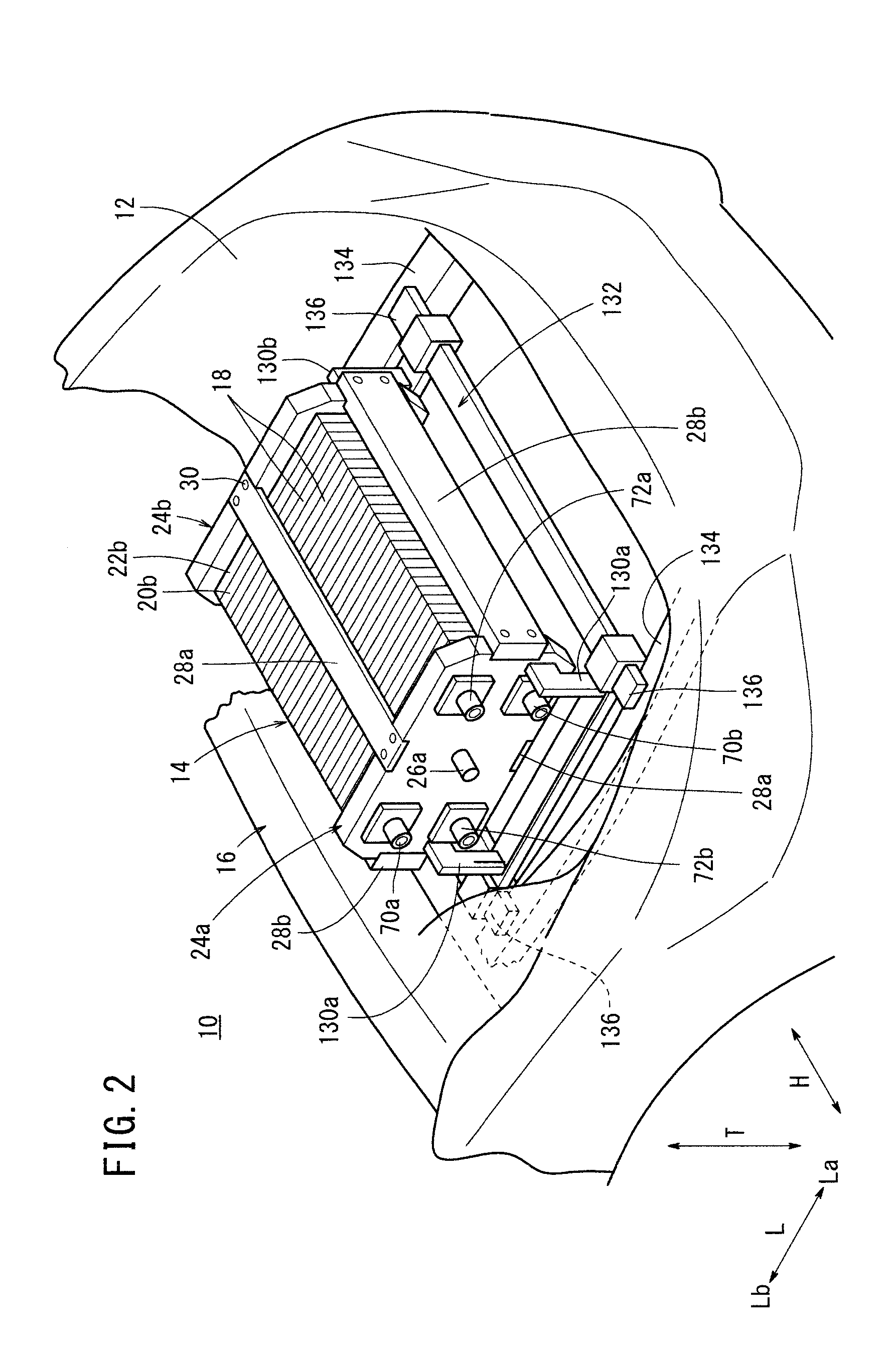
[0026]The fuel cell stack 14 is formed by stacking a plurality of fuel cells 18 upright in a vehicle width direction of the fuel cell vehicle 10 indicated by an arrow H intersecting with a vehicle length direction thereof indicated an arrow L. The fuel cells 18 may be stacked in a height direction of the fuel cell vehicle 10 indicated by an arrow T.
[0027]As shown in FIGS. 2 and 3, at one end of the fuel cells 18 in the stacking direction, a first terminal plate 20a is provided. A first insulating plate 22a is provided outside the first terminal plate 20a, and a first end plate 24a is provided outside the first insulating plate 22a. At the other end of the fuel cells 18 in the stacking direction, a second terminal plate...
second embodiment
[0079]FIG. 6 is a side view showing main components of a fuel cell vehicle 150 according to the present invention.
[0080]The constituent elements that are identical to those of the fuel cell vehicle 10 according to the first embodiment are labeled with the same reference numerals, and description thereof will be omitted. Likewise, also in third and fourth embodiments described later, constituent elements that are identical to those of the fuel cell vehicle 10 according to the first embodiment are labeled with the same reference numerals, and description thereof will be omitted.
[0081]In the fuel cell vehicle 150, a traction motor 126 and an air motor 90 form an impact relaxing mechanism 152. The air motor 90 and the traction motor 126 are arranged next to each other in the front-rear direction of the vehicle, and the shaft centers O1 and O2 of the air motor 90 and the traction motor 126 are arranged on the same plane in a horizontal direction.
[0082]In the impact relaxing mechanism 152...
third embodiment
[0086]As shown in FIGS. 8 and 9, a fuel cell vehicle 160 according to the present invention includes an impact relaxing mechanism 162. The impact relaxing mechanism 162 includes various components of the oxygen-containing gas supply apparatus 80 such as the air compressor 88, the inlet seal valve 98a, the humidifier 94, and the outlet seal valve 98b. These components are arranged in the front-rear direction of the vehicle (i.e., in the direction indicated by an arrow L).
[0087]In the impact relaxing mechanism 162, the length S5 in the front-rear direction of the vehicle is larger than the length S1 of the fuel cell stack 14 in the front-rear direction of the vehicle. The fuel cell stack 14 is disposed within the range of the length S5 of the impact relaxing mechanism 162, and the impact relaxing mechanism 162 protrudes outward beyond one side portion of the fuel cell stack 14 in the width direction (see FIG. 9).
[0088]In the third embodiment, the impact relaxing mechanism 162 is provi...
PUM
 Abstract
Description
Claims
Application Information
 - R&D
- Intellectual Property
- Life Sciences
- Materials
- Tech Scout
- Unparalleled Data Quality
- Higher Quality Content
- 60% Fewer Hallucinations
Browse by: Latest US Patents, China's latest patents, Technical Efficacy Thesaurus, Application Domain, Technology Topic, Popular Technical Reports.
© 2025 PatSnap. All rights reserved.Legal|Privacy policy|Modern Slavery Act Transparency Statement|Sitemap|About US| Contact US: help@patsnap.com