Self-Propelled Cold Milling Machine, As Well As Method For Milling Off And Transporting Away A Milled-Off Stream Of Material

a self-propelled, cold milling machine technology, applied in transportation and packaging, roads, highway maintenance, etc., can solve the problems of inability to load and transport material onto trucks as intended, inability to perform additional sweeping operations, and inability to compute the actual parabolic trajectory and the point of impingement. , to achieve the effect of improving reproducibility

Active Publication Date: 2015-01-29
WIRTGEN GMBH
View PDF3 Cites 3 Cited by
  • Summary
  • Abstract
  • Description
  • Claims
  • Application Information

AI Technical Summary

Benefits of technology

[0011]It is therefore the object of the invention to specify a cold milling machine as well as a method for milling off and transporting away a milled-off stream of material in which the discharge of the milled-off stream of material can be computed in an improved fashion and performed with improved reproducibility.
[0014]During operation, the shielding device is preferably arranged in an operating position whereas it may be arranged in a transport position for transport of the cold milling machine. This offers the advantage of the overall length of the machine not being unnecessarily increased during transport or when moving the machine to a different operating site.
[0023]The lateral sections of the shielding device may feature a height which increases downwards in conveying direction. This offers the advantage of ensuring lateral shielding also at the lowest possible conveying speed.

Problems solved by technology

The computability of the actual parabolic trajectory and the point of impingement may be impaired by outer environmental influences, such as strong wind or pressure waves created by traffic moving alongside the construction site.
As a result,parts of the flow of material cannot be loaded onto the truck and transported away as intended, which requires additional sweeping operations to be performed;the traffic moving alongside a construction site may be impaired by particles of the milled material leaving the main stream of material and, in extreme cases, damage may be caused to passing vehicles.

Method used


Image

  • Self-Propelled Cold Milling Machine, As Well As Method For Milling Off And Transporting Away A Milled-Off Stream Of Material
  • Self-Propelled Cold Milling Machine, As Well As Method For Milling Off And Transporting Away A Milled-Off Stream Of Material
  • Self-Propelled Cold Milling Machine, As Well As Method For Milling Off And Transporting Away A Milled-Off Stream Of Material

Examples


Embodiment Construction

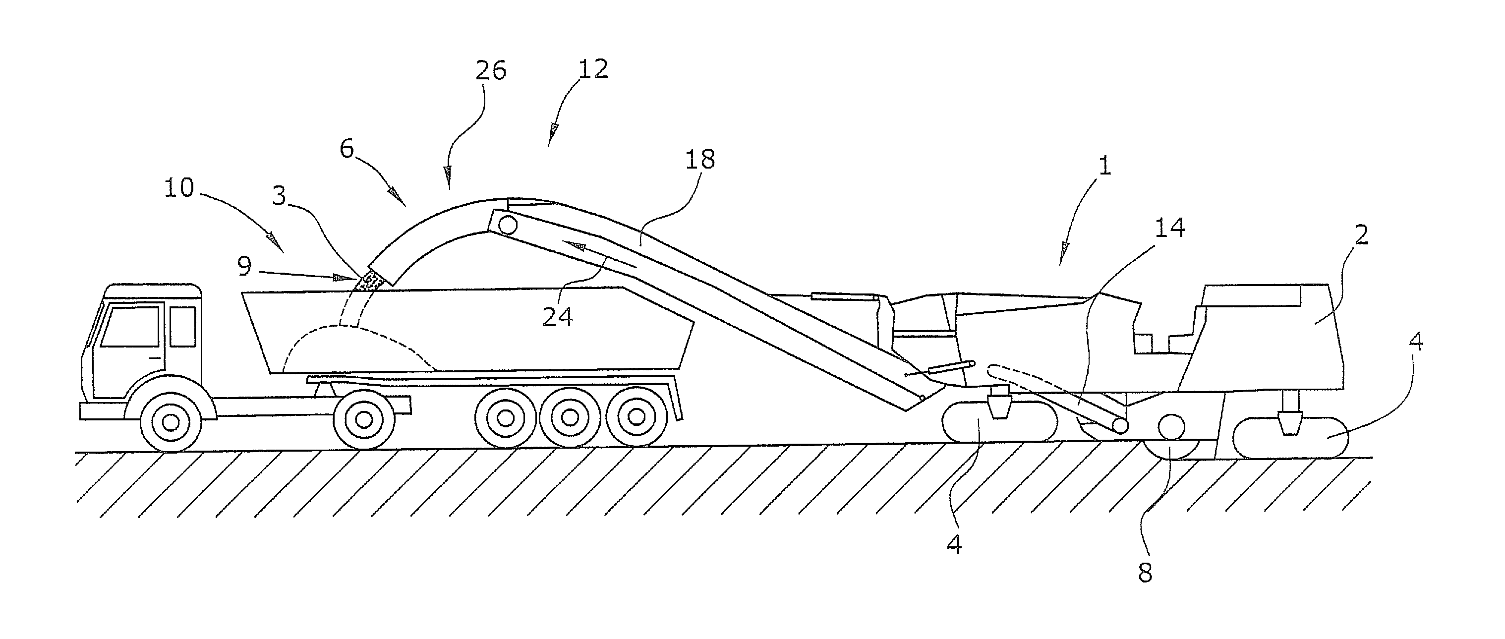
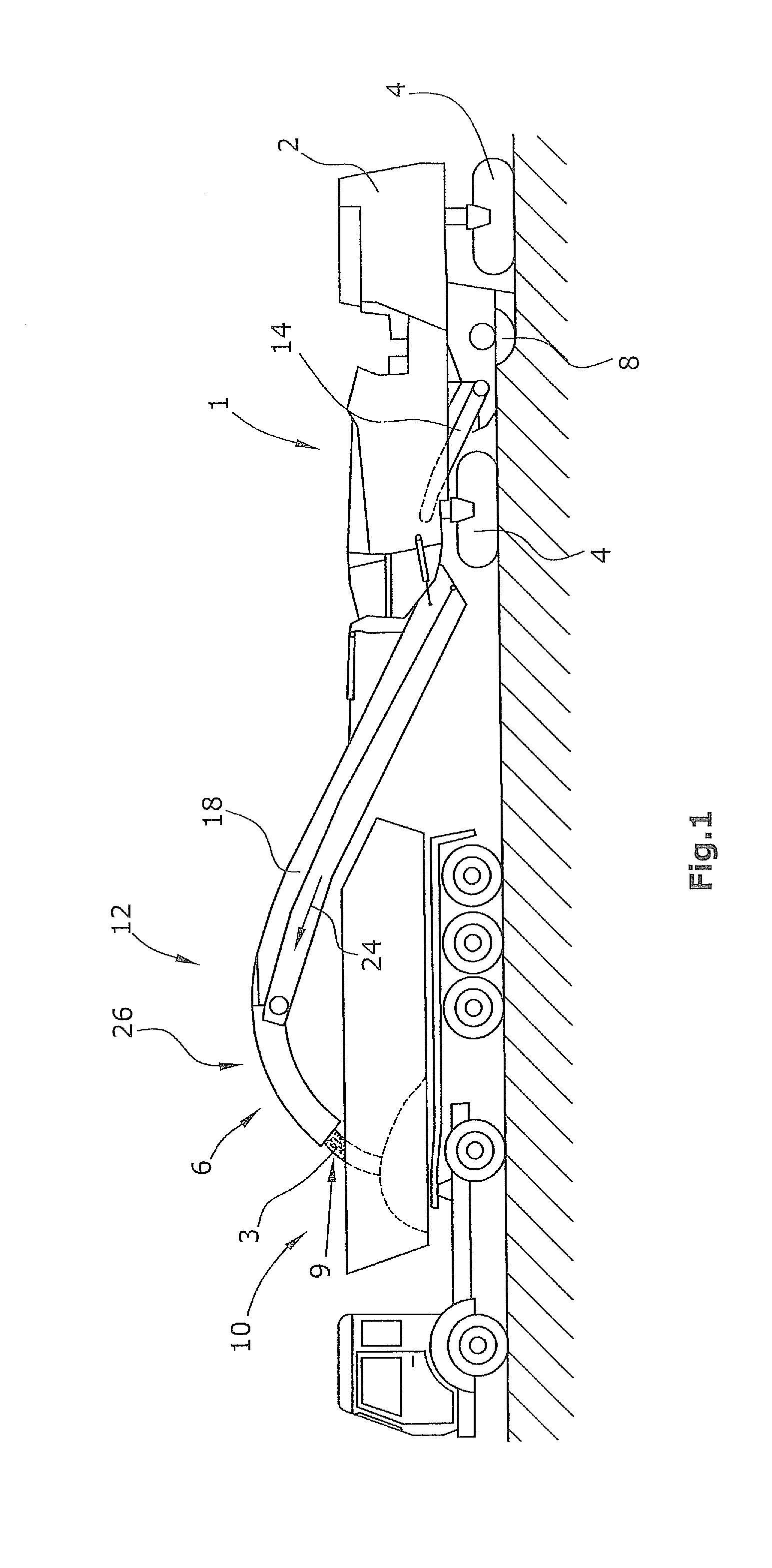
[0036]A milling machine 1 for working ground surfaces is shown in FIG. 1 in the embodiment of a front-loading milling machine. It is understood that the invention is also applicable to other types of milling machines provided with no less than one conveying device, in particular transport conveyor 18.

[0037]The milling machine 1 is used to mill off ground surfaces, in particular roadways made of asphalt, concrete or the like.

[0038]The milling machine 1 comprises a machine frame 2 which is supported by crawler tracks 4 or wheels. A milling drum 8, which extends transversely to the direction of travel, is mounted in the machine frame 2. It is understood that a corresponding transport conveyor 18 may also be mounted, for example, as the single conveying device on a rear-loading milling machine.

[0039]With a rear-loading milling machine, the milled-off material 3 is discharged against the direction of travel whereas with a front-loading milling machine in accordance with FIG. 1, the mille...


PUM


Abstract

In a self-propelled cold milling machine, in particular cold milling machine, for working ground surfaces, with a milling drum supported at a machine frame, no less than one conveying device arranged at the machine frame which accepts the milled-off material from the milling drum and discharges said milled-off material, in conveying direction, at a discharge end along a parabolic trajectory onto a point of discharge, it is provided for the following features to be achieved: that the conveying device comprises a shielding device at the discharge end, where said shielding device shields the material milled off and leaving the conveying device without influencing the parabolic trajectory on a part of the path to the point of discharge at least by means of lateral sections.

Description

BACKGROUND OF THE INVENTION[0001]1. Field of the Invention[0002]The invention relates to a self-propelled cold milling machine for working ground surfaces, in particular roadways, as well as to a method for milling off and transporting away a milled-off stream of material of a cold milling machine.[0003]2. Description of the Prior Art[0004]A front-loading milling machine is known, for example, from EP 1 507 925, FIG. 1. The known cold milling machines feature a machine frame supported by crawler tracks or wheels. A milling drum is mounted in the machine frame transversely to the direction of travel. In order to achieve the completest possible removal of the milled-off material, the milling drum is generally enclosed by a housing, the wall of which pointing in the direction of travel is designed as a covering blade with an opening for the milled-off material. The material worked off by the milling drum is accepted by a first transport conveyor which transfers the worked-off material,...

Claims


Application Information

Patent Timeline
Patent Type & Authority Applications(United States)
IPC IPC(8): E01C23/088E01C23/12
CPCE01C23/127E01C23/088B65G21/08B65G47/44
Inventor LEY, HERBERTVERHAELEN, PHILIPBARIMANI, CYRUSHAHN, GUNTER
Owner WIRTGEN GMBH
Why Eureka
Try Eureka