
Electronic hinged safety switch

a safety switch and hinge technology, applied in the direction of hinges, contact mechanisms, instruments, etc., can solve the problems of increasing the installation cost and circuit complexity of the electrical system, the use of mechanical commutators cannot be easily installed in safety plants, and the inability to generate electric signals easily. , to achieve the effect of high efficiency and relatively cost-effectiv

Active Publication Date: 2015-01-29
PIZZATO ELETTRICA
View PDF0 Cites 2 Cited by
  • Summary
  • Abstract
  • Description
  • Claims
  • Application Information

AI Technical Summary

Benefits of technology

The present invention aims to provide an electronic hinged safety switch that is highly efficient and cost-effective. Further, it offers quick and fully automatic enabling and disabling of the safety switch by the plant during maintenance.

Problems solved by technology

A first drawback of this prior art arrangement is that the use of mechanical commutators does not easily allow generation of electric signals with additional information concerning the position of the barrier or the state of the switch.
This is because mechanical commutators only allow switching of electrical contacts associated with safety circuits and cannot determine any inconsistent switching states of the contacts or wiring or contact unit failures.
A further drawback of this arrangement is that switches with mechanical commutators cannot be easily installed in safety plants that use a data bus or a field bus connected to an electronic control unit.
The installation of hinged safety devices with analog contact units requires an appropriate analog-to-digital conversion interface, such as AS-i or the like, to be interposed between the bus and the contacts, which will increase installation costs and circuit complexity of the electrical system.

Method used


Image

  • Electronic hinged safety switch
  • Electronic hinged safety switch
  • Electronic hinged safety switch

Examples


Embodiment Construction

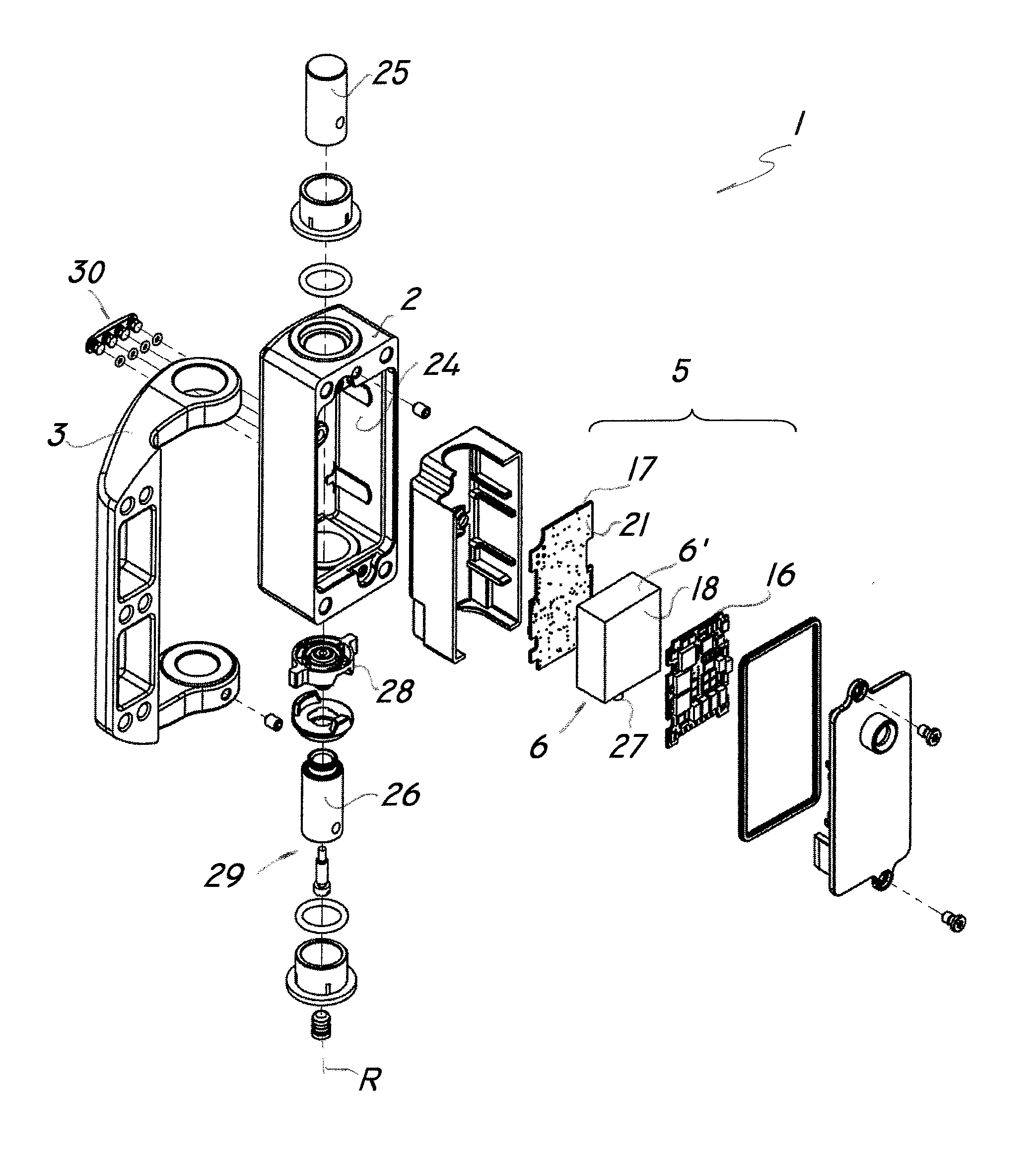
[0030]Referring to the above mentioned figures, a multifunctional electronic hinged safety switch, generally designated by numeral 1, is adapted for use in a protection barrier B which is designed to bound a hazardous area of a machine or a plant.

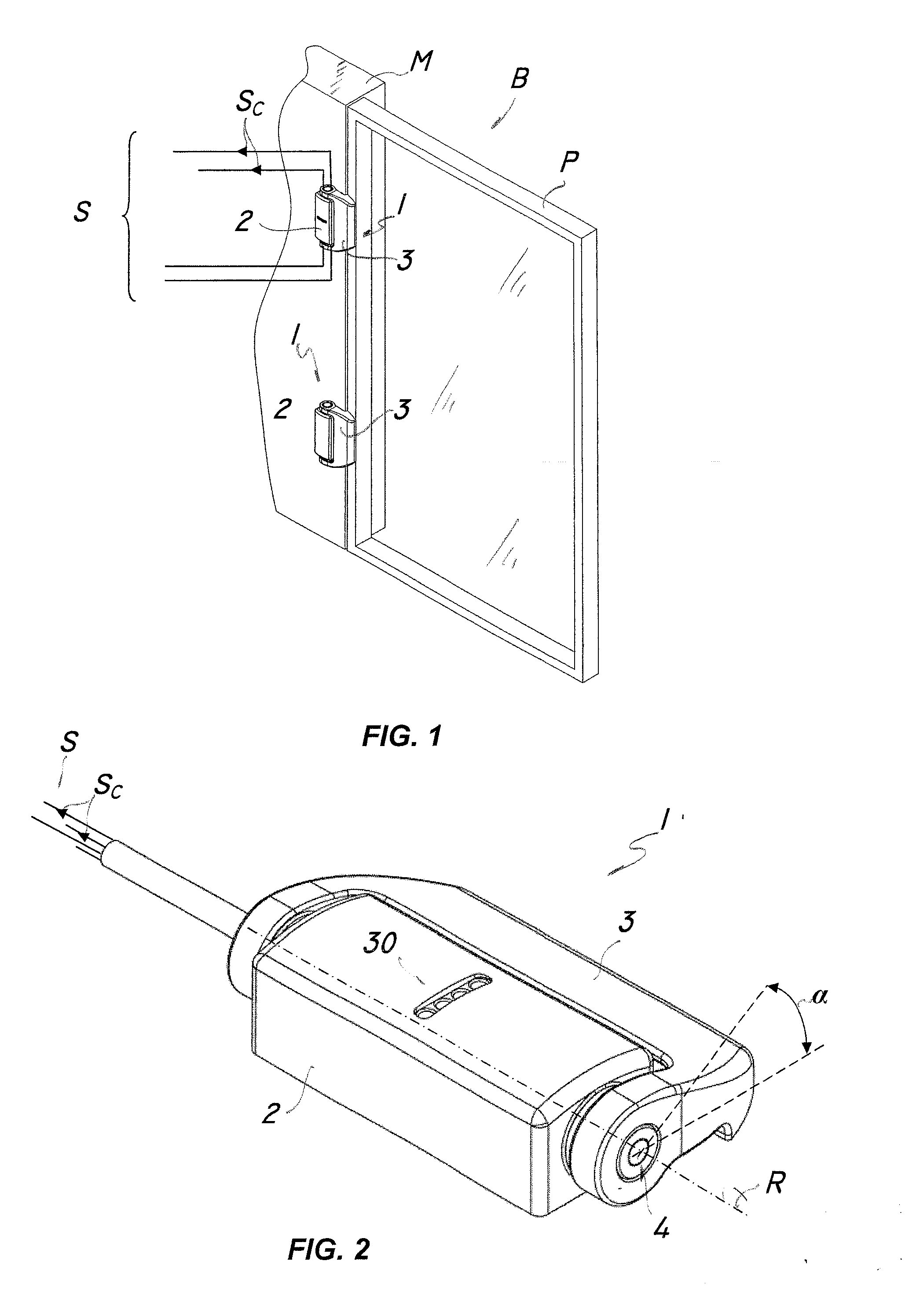
[0031]Particularly, as best shown in FIG. 1, the protection barrier B may comprise a stationary part M which is designed to be secured to the ground or the frame of the machine or plant, and a pivotal part P, such as a door or over hinged to the stationary part M.

[0032]Furthermore, the barrier B is equipped with one or more electric safety circuits S for signaling that the door D has been opened and / or closed, by varying an appropriate electric signal.

[0033]The multifunctional hinged switch 1 of the invention comprises, as best shown in FIG. 2, a substantially box-like fixed member 2 designed to be secured to a stationary part M of the protection barrier B and a movable member 3 designed to be secured to a pivotal part P of the barrier B an...


PUM


Abstract

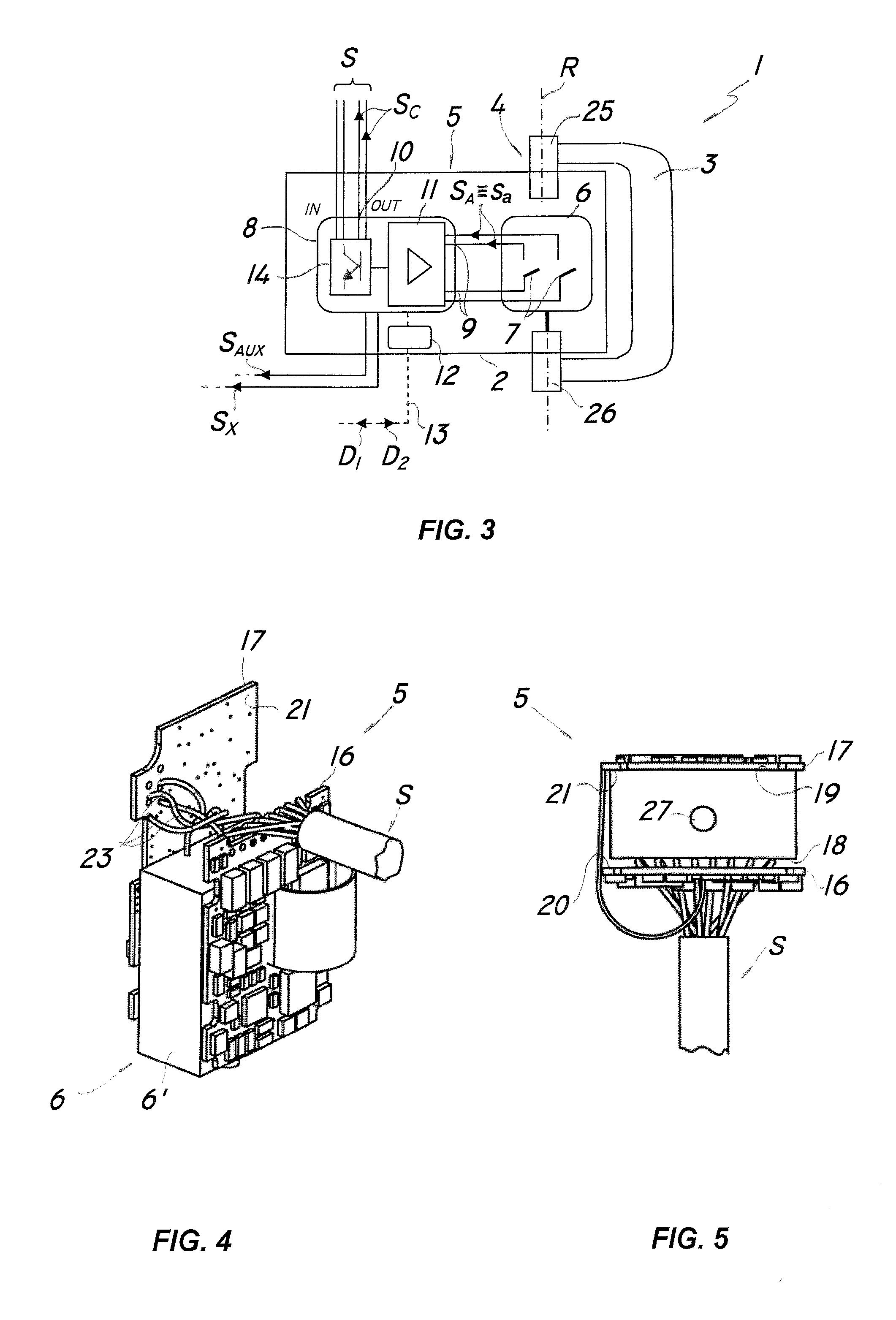
An electronic hinged safety switch adapted for installation on protection barriers (B) of machines and / or automatic plants having one or more electric safety circuits (S). The switch comprises a substantially box-like fixed member (2) designed to be secured to a stationary part (M) of a protection barrier (B) and a movable member (3) designed to be secured to a pivotal part (P) of the protection barrier (B) and coupled to the fixed member (2) through hinge means (4). Sensing means (5) are housed in said box-like fixed member (2) for interacting with the hinge means (4) to send an electric control signal (SC) to one or more electric safety circuits (S) at a predetermined switching angle (α). The sensing means (5) comprise at least one sensor for generating a corresponding actuation signal (SA) at the switching angle (α), and an electronic control unit (8) operatively connected to at least one sensor (6). The electronic control unit (8) has at least one input (9) electrically connected to said sensor (6) for receiving the actuation signal (SA) and at least one output (10) connected to the electronic safety circuits (S) for generating the electric control signal (SC) in response to the actuation signal (SA).

Description

FIELD OF THE INVENTION[0001]The present invention generally finds application in the field of electric safety devices and particularly relates to an electronic hinged safety device.BACKGROUND ART[0002]Hinged safety switches are known to be used in plants or machines having areas or rooms bounded by protection barriers, and containing mechanical moving members or hazardous devices.[0003]Particularly, these safety switches are mounted to a protection barrier having a fixed part integral with the machine or plant, and a movable panel designed to be opened by an operator.[0004]Hinged safety switches have casing designed to be secured to the fixed part of the barrier and a movable part, which can pivot relative to the enclosure, and is designed to be secured to the panel.[0005]Furthermore, the switch comprises an electrical commutator and an actuator, which is adapted to interact with such commutator upon pivotal movement of the movable part.[0006]As the panel is opened and / or closed, th...

Claims


Application Information

Patent Timeline
IPC IPC(8): G08B5/36
CPCG08B5/36H01H3/162H01H3/42E05D11/0081
Inventor PIZZATO, MARCOPIZZATO, GIUSEPPE
Owner PIZZATO ELETTRICA
Learn More