
Firewood-, coal- or biomass-economizing stove with multiple combustion chamber, thermal insulation, cooking hob and chimney

a technology of multiple combustion chambers and stoves, which is applied in the direction of domestic stoves or ranges, heating types, lighting and heating apparatus, etc., can solve the problems of stoves not being able to use indoors as the interior, not having the means to harness the heat of combustion fumes, and not being able to harness heat. , to achieve the effect of reducing the risk of burns and avoiding health problems

Inactive Publication Date: 2015-02-05
RODRIGUEZ GONZALEZ BERNARDO +1
View PDF21 Cites 2 Cited by
  • Summary
  • Abstract
  • Description
  • Claims
  • Application Information

AI Technical Summary

Benefits of technology

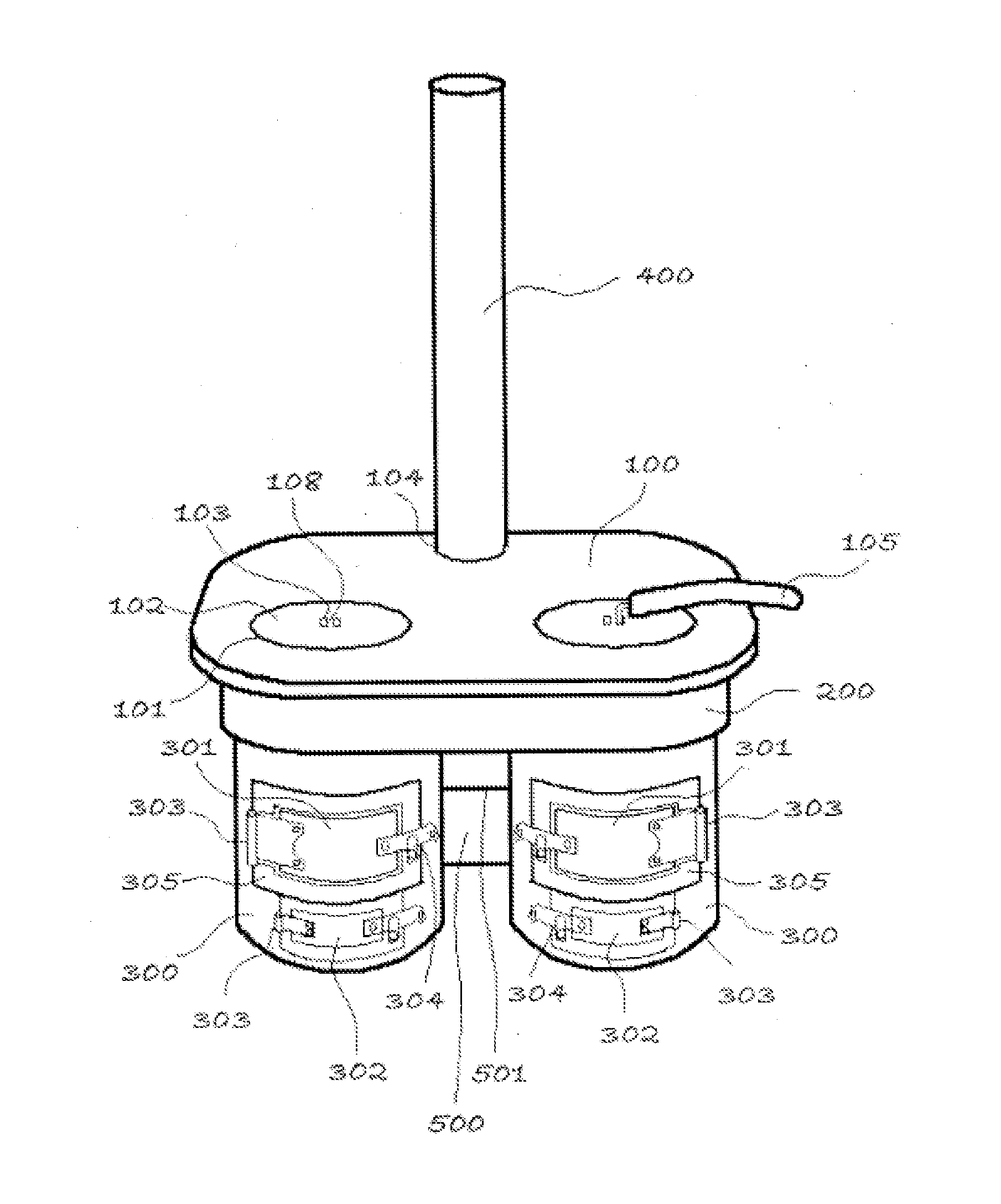
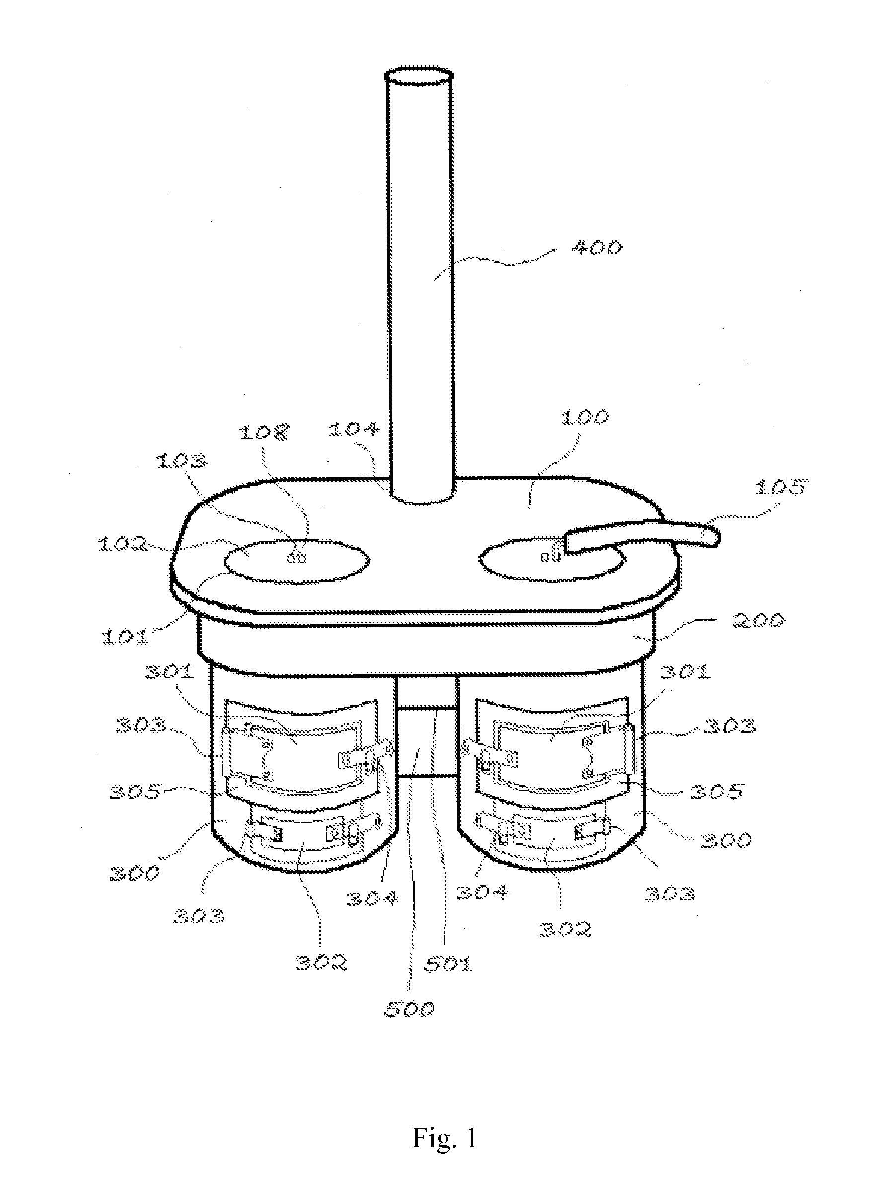
The present invention is a stove that can burn wood, coal, or biomass and extract the fumes through multiple combustion chambers and a hot fumes distribution chamber connected to a chimney. This stove reduces health risks associated with open fire cooking, allows for use in confined spaces, and provides thermal insulation to prevent burns. Additionally, the stove allows for simultaneous cooking of multiple containers and uses the fumes produced during combustion as a griddle, eliminating the need to remove food containers from fire.

Problems solved by technology

The problem with this stove is having a single burner, allowing the heating of only one container of food at a time and not having the means to harness the heat of the fumes produced by combustion.
In this case, the fumes produced during combustion are directed into the cavity, to be expelled after through the chimney, so that the cavity retains heat to maintain or raise the heat in the combustion chamber itself and has no means to harness the heat for other purposes such as providing a hot griddle.
This stove does not allow its use indoors as the interior of a home because it has no means for directing the fumes produced by the combustion.

Method used


Image

  • Firewood-, coal- or biomass-economizing stove with multiple combustion chamber, thermal insulation, cooking hob and chimney
  • Firewood-, coal- or biomass-economizing stove with multiple combustion chamber, thermal insulation, cooking hob and chimney
  • Firewood-, coal- or biomass-economizing stove with multiple combustion chamber, thermal insulation, cooking hob and chimney

Examples


Embodiment Construction

[0013]The present invention consists of a vertical wood, coal or biomass burning stove, which has been implemented with technical adaptations that make it different from all existing stoves of this type, giving it useful advantages and allowing the user to cook more than one meal at a time, while avoiding the risk of skin burns and poisoning by fumes inhalation, and providing a plate for use by way of a griddle.

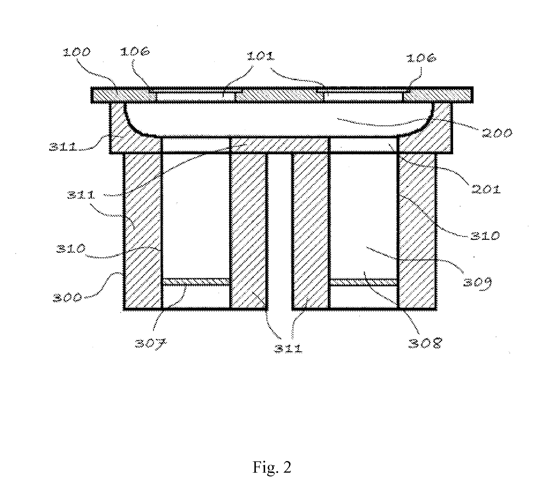
[0014]The stove consists of a piece of furniture comprising a prismatic hollow housing, being substantially rectangular or square, wherein its sides are substantially longer than its height. Said hollow housing forms a chamber (200) for the distribution of hot fumes produced by combustion, which is supported by a plurality of pedestals (300), said pedestals being preferably cylindrical, wherein combustion takes place and which contain some of the elements of said vertical stove, wherein said pedestals (300) are located below the hot fumes distribution chamber (200), adjacent ...


PUM


Abstract

A “rocket” stove that has a plurality of vertical cylindrical cavities containing a combustion chamber, a fuel compartment and a chimney. The vertical cylindrical cavities are connected to a hot-gas chamber where the gases are utilized to heat a hob used in the manner of a griddle. The hob has apertures over the vertical cylindrical cavities, over which the food containers to be heated are placed. The hot-gas chamber has an opening and an exhaust pipe for evacuating the gases from the environment where the stove is used. The stove has a thermal-insulation covering placed between the interior walls thereof and the exterior in order to prevent burns. The exhaust pipe prevents intoxication by smoke inhalation, which commonly arises when cooking over an open fire.

Description

OBJECT OF THE INVENTION[0001]The present invention relates to a wood, coal or biomass burning stove, which allows to extract the produced fumes by means of a plurality of combustion chambers communicated with a hot fumes distribution chamber in combination with a chimney, avoiding the health problems associated with poisoning by fumes from cooking over an open fire, allowing the use of the stove in confined spaces. A second object of the invention is to reduce the risk of burns by means of thermal insulation between the outside of the stove housing and its internal elements, where the heat is produced. A third object of the invention is to enable the cooking of food contained in a plurality of containers simultaneously. A fourth object of the invention is to provide a surface that is heated by the fumes produced during the combustion for cooking and heating food, particularly tortillas, using this surface as a griddle, not being necessary to remove food containers from fire.BACKGROU...

Claims


Application Information

Patent Timeline
Patent Type & Authority Applications(United States)
IPC IPC(8): F24B1/00F24B13/00F24B1/02
CPCF24B1/003F24B13/004F24B1/026F23B80/04F24B1/26F23B10/00F23J11/02F23B20/00Y02A40/928
Inventor VILLARREAL ESCAMILLA, REYNALDORODRIGUEZ GONZALEZ, BERNARDOWEST, BENJAMIN DOUGLAS
Owner RODRIGUEZ GONZALEZ BERNARDO
Learn More