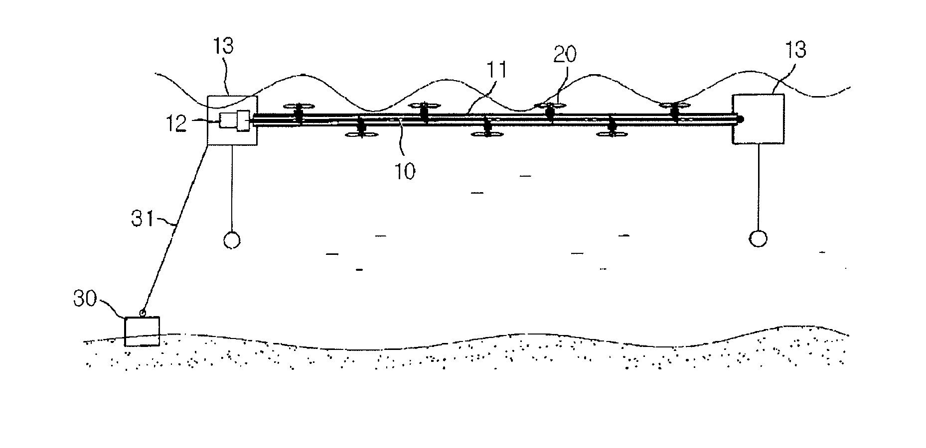
Wave power generating apparatus
a technology of power generation apparatus and wave power, which is applied in the direction of mechanical equipment, electric generator control, machines/engines, etc., can solve the problems of weak structural safety of above apparatus, limited continuous generation power, and weak structural safety of apparatus, so as to reduce the power and speed of tsunami, the effect of continuous generation power and efficient generation
- Summary
- Abstract
- Description
- Claims
- Application Information
AI Technical Summary
Benefits of technology
Problems solved by technology
Method used
Image

Examples
Embodiment Construction
[0056]
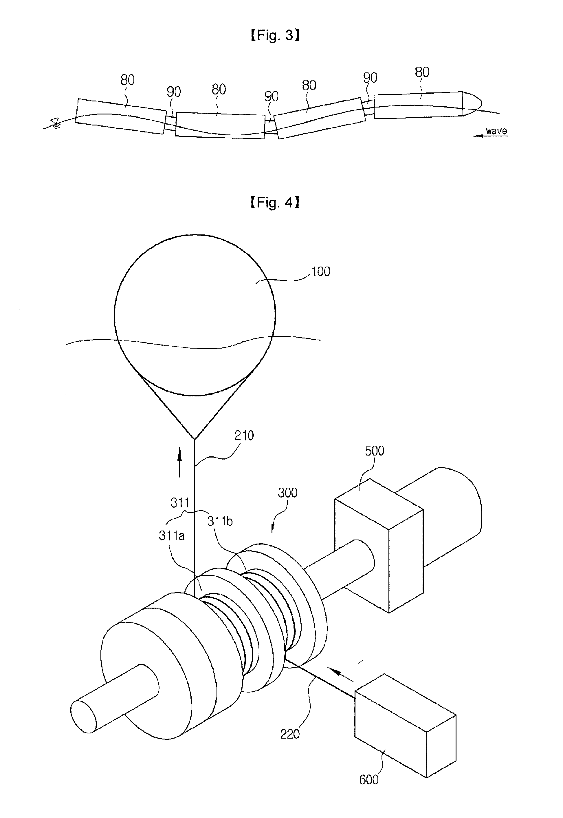
1000: wave power generating100: floatapparatus of the present disclosure101: inlet hole102: outlet hole103: channel110: float support rope120: main support rope130: branched support rope140: collision plate150: hinge160: elastic unit210: power transmission rope210a: inclined power transmission220: return roperope230: second return rope300: power transmission unit310: one-directional latchet clutch311: two-stage pulley311a: first pulley311b: second pulley320: contact roller unit321: roller322: central shaft323: ballast324: torsion spring10: latchet wheel11: latchet12: inner groove13: shaft hole20: pole fixing plate21: shaft coupling hole22: key23: key groove30: pole31: hinge32: mount groove33: end portion34: rotating roller40: elastic unit400: power transmission shaft410: universal joint500: generator600: return mechanism610: fixed plate611: hinge620: pendulum621: roller622: torsion spring623: gear630: ballast640: roller641: hollow642: shaft650: clockwork spring660: pipe670: co...
PUM
 Abstract
Description
Claims
Application Information
 - Generate Ideas
- Intellectual Property
- Life Sciences
- Materials
- Tech Scout
- Unparalleled Data Quality
- Higher Quality Content
- 60% Fewer Hallucinations
Browse by: Latest US Patents, China's latest patents, Technical Efficacy Thesaurus, Application Domain, Technology Topic, Popular Technical Reports.
© 2025 PatSnap. All rights reserved.Legal|Privacy policy|Modern Slavery Act Transparency Statement|Sitemap|About US| Contact US: help@patsnap.com