Grid scale energy storage systems using reheated air turbine or gas turbine expanders

a technology of gas turbine expansion and energy storage system, which is applied in the direction of fluid coupling, rotary clutch, servomotor, etc., can solve the problem of not having an energy storage system that can shift the power output of conventional generation, and the charging time of a thermal storage system is approximately 15-18 hours

Active Publication Date: 2016-03-31
POWERPHASE
View PDF13 Cites 6 Cited by
  • Summary
  • Abstract
  • Description
  • Claims
  • Application Information

AI Technical Summary

Benefits of technology

[0005]The present invention provides a system which can charge and discharge multiple times each day, and therefore is able to capture both energy peaks and troughs on any given day. The present invention is a direct injection air system and avoids the majority of the issues with ambient temperature, and therefore has the capacity to generate power from the gas turbine during the morning and evening peak usage periods. In addition, the present invention has two modes of discharging that can be used independently or together, which allows the energy storage system to discharge power to the grid even if the gas turbine is not running.

Problems solved by technology

Today, there is no energy storage system available that can shift the power output of conventional generation.
In California, thermal storage using inlet chilling has been one method of shifting the power of gas turbine generation, however, there are significant drawbacks to this chilling system.
The first drawback is with respect to the charging time of a thermal storage system, which can take approximately 15-18 hours, and therefore can only discharge once per day.
This can be overcome with larger chilling systems, however, such systems add considerable expense.
The second drawback is that chillers work on the principal of cooling the inlet temperature of the gas turbine with a lower temperature limit of about 55 F., and, unfortunately, the peak power output is required typically between 5 am and 9 am and then again between 6 pm and 10 pm, which are out of phase with the hot part of the day.

Method used


Image

  • Grid scale energy storage systems using reheated air turbine or gas turbine expanders
  • Grid scale energy storage systems using reheated air turbine or gas turbine expanders
  • Grid scale energy storage systems using reheated air turbine or gas turbine expanders

Examples


Embodiment Construction

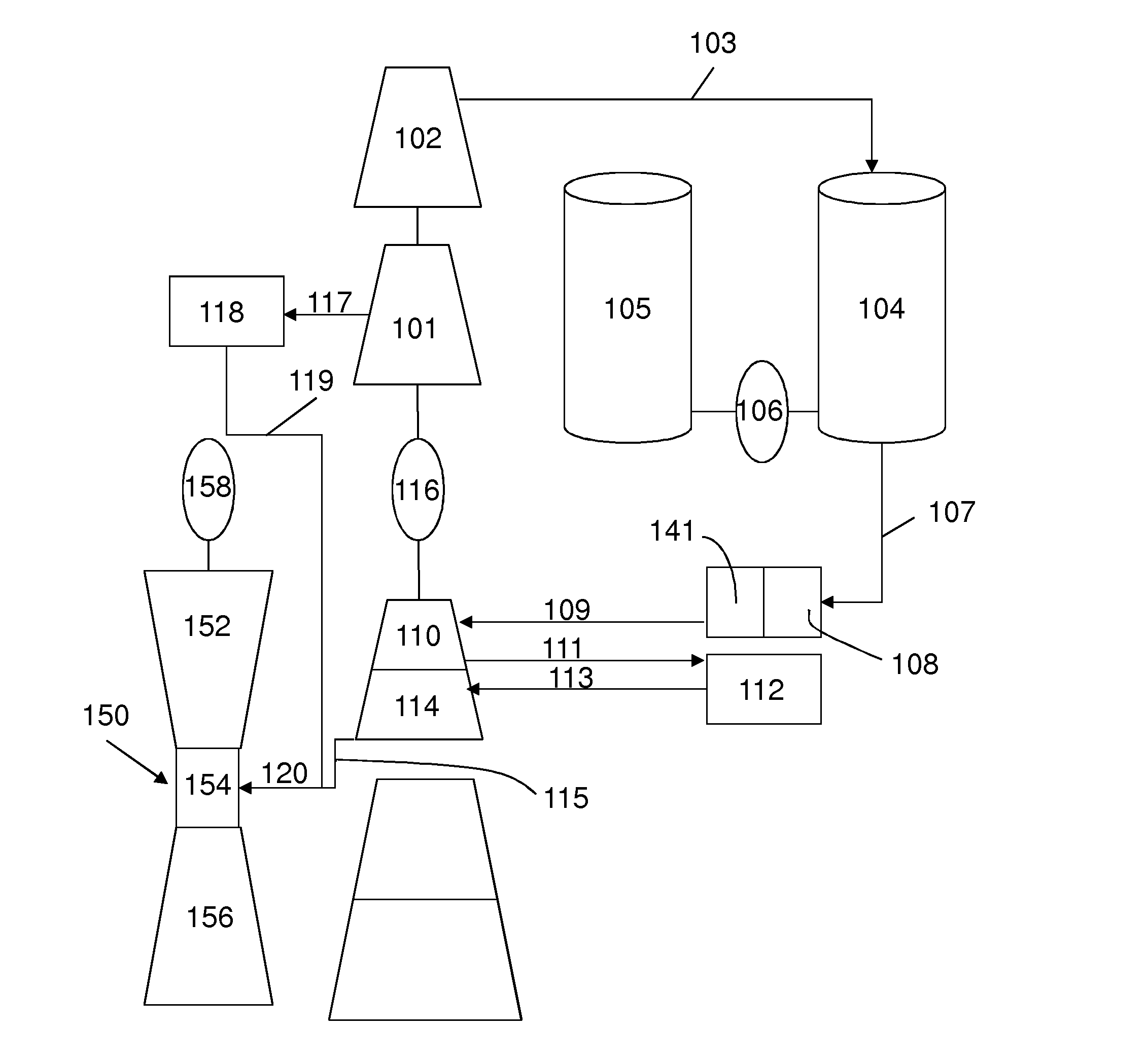
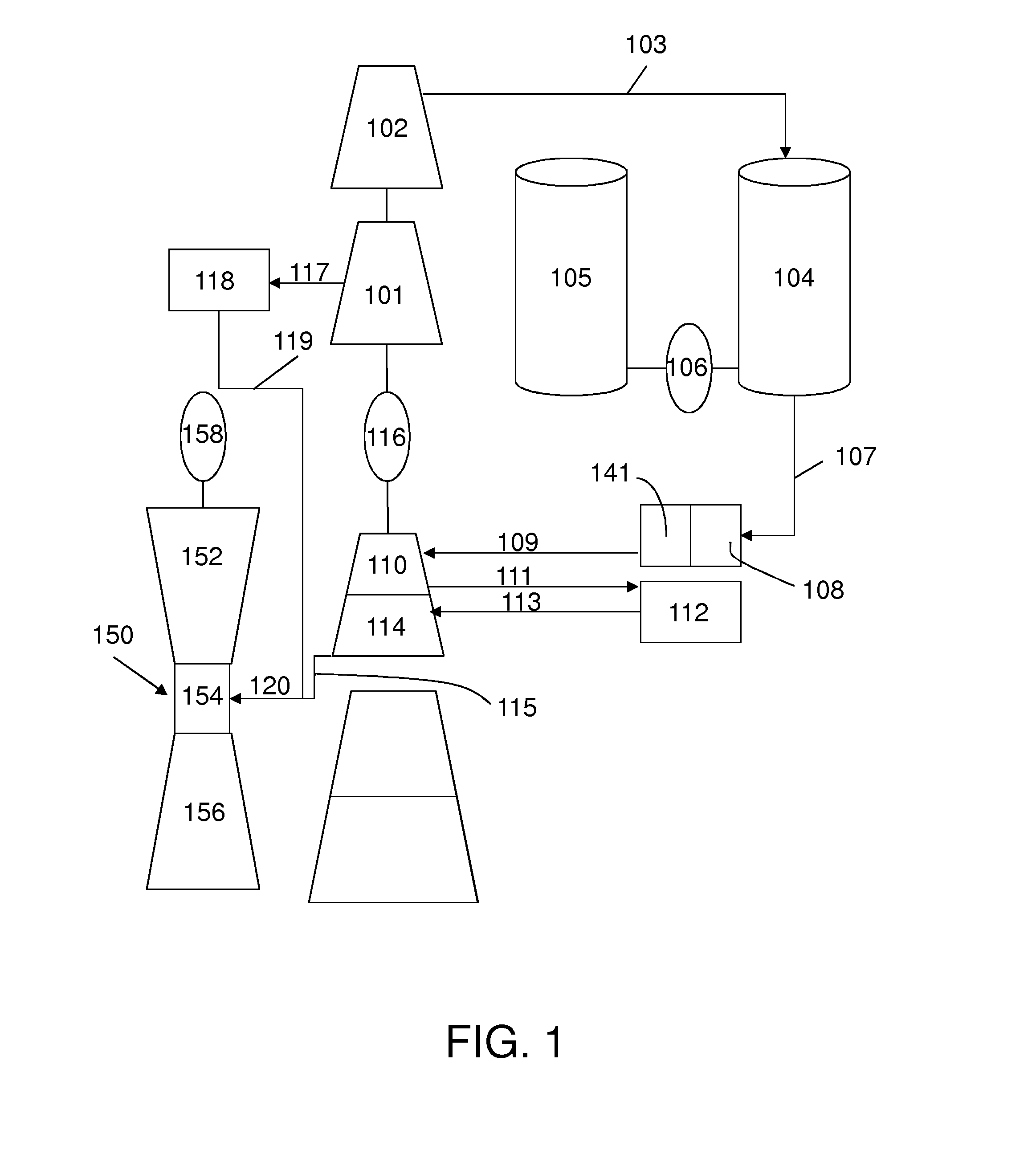
[0014]The present invention relates to methods and systems of compressing air, storing the air, and discharging the air through an air turbine, a gas turbine, or both to improve operations at a power plant.

[0015]Referring initially to FIG. 1, an embodiment of the present invention compresses ambient air through a multi-stage compressor. The compressor comprises two separate pieces of equipment, a low pressure compressor (LPC) 101 and a high pressure compressor (HPC) 102. Both the LPC 101 and HPC 102 are driven by the same motor / shaft system and can be de-coupled from one another via a clutch (not shown), allowing the LPC 101 to be driven separately from the HPC 102. Alternatively, the LPC 101 and HPC 102 can be driven with two different electric motors. Further, the multi-stage compressor can be an intercooled compressor where intercooling occurs after each stage of compression. For example, in an embodiment of the present invention, the LPC 101 comprises four stages with correspond...


PUM


Abstract

Electrical power systems, including generating capacity of a gas turbine, where additional power is generated from an air expander and gas turbine simultaneously from a stored compressed air and thermal system.

Description

CROSS-REFERENCE TO RELATED APPLICATIONS[0001]This application claims priority to U.S. Provisional Patent Application Ser. No. 62 / 055,247, filed on Sep. 25, 2014, which is hereby incorporated by reference in its entirety.TECHNICAL FIELD[0002]The invention relates generally to electrical power systems and energy storage systems, including generating capacity of a gas turbine, independent air turbines and more specifically to methods of integrating compressed air energy storage and stored heat energy.BACKGROUND OF THE INVENTION[0003]As the renewable energy market increases there is a dynamic balancing act that takes place every day between load, renewable power and conventional generation. For example, in the California energy market, solar energy use is significantly changing the dispatch of conventional generation. During the middle of the day, when load peaks, solar power is also at its peak and thus suppresses the traditional generation required during this peak load period. Conseq...

Claims


Application Information

Patent Timeline
Patent Type & Authority Applications(United States)
IPC IPC(8): F15B11/08F15B21/00
CPCF15B21/001F15B11/08F02C1/105F02C6/16Y02E60/16
Inventor KRAFT, ROBERT, J.KRAFT, MATTHEW
Owner POWERPHASE
Why Eureka
Try Eureka