Methods of operating dual fed systems

a dual-fed system and feed technology, applied in the direction of single-network parallel feeding arrangement, ac-dc network circuit arrangement, etc., can solve the problem that the diode front end of each power converter b>34/b> still does not allow control of the amount of power supplied by each ac busbar, so as to minimise total power usage, minimise exhaust emissions, and minimise total power usage

Active Publication Date: 2015-02-05
GE ENERGY POWER CONVERSION TECH
View PDF3 Cites 19 Cited by
  • Summary
  • Abstract
  • Description
  • Claims
  • Application Information

AI Technical Summary

Benefits of technology

[0032]A dual fed marine propulsion system makes it possible to optimise thrust allocation between propulsion motors in a way that is similar to that used in conventional dynamic positioning (DP) systems and then share or allocate the required power between generators to minimise exhaust emissions. More particularly, if a dual fed marine propulsion system includes a plurality of propulsion motors then the method may further comprise the steps of selecting a desired total power usage and allocating a thrust demand between the propulsion motors to achieve the desired total power usage. Preferably the thrust demand will be allocated to minimise total power usage. The thrust demand is typically provided by a controller of a DP system.
[0033]Similarly, if the system being operated by the method of the present invention is any other dual fed system that includes a plurality of electrical loads then the method may further comprise the steps of selecting a desired total power usage and allocating an output demand between the electrical loads to achieve the desired total power usage. Preferably, the output demand will be allocated to minimise total power usage.

Problems solved by technology

As mentioned above, the minimum power solution for thrust allocation requires that thrust is shared in proportion to the rated power of each thruster and this is not possible in the marine propulsion system of FIG. 1.
However, the diode front end of each power converter 34 still does not allow control of the amount of power that is supplied by each ac busbar.

Method used


Image

  • Methods of operating dual fed systems
  • Methods of operating dual fed systems
  • Methods of operating dual fed systems

Examples


example

(3)

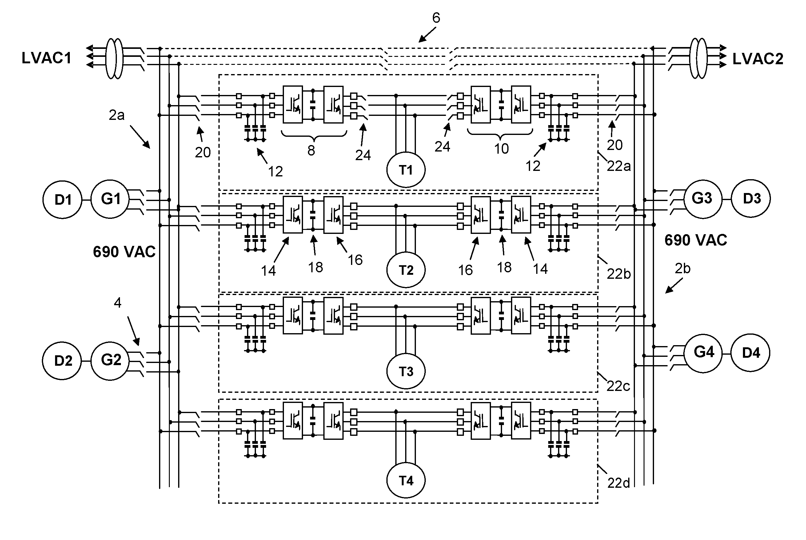
[0070]The dual fed marine propulsion system shown in FIG. 3 allows the thrust allocation to achieve minimum power, i.e. all four thrusters T1-T4 supply equal thrust of 30.74 kN and request equal power of about 0.17 MW with a total power requirement of about 0.68 MW. The power allocation will minimise NOx emissions by sharing power between the first and second ac busbars 2a, 2b so that generators G1, G2 each output about 0.3 MW (in other words they operate at the highlighted minimum of the emissions curve) and the remaining two generators G3, G4 each output about 0.04 MW. Referring to FIG. 5 then diesel engines D1, D2 will each produce NOx emissions of about 0.162 kg / h and diesel engines D3, D4 will each produce NOx emissions of about 0.127 kg / h.

[0071]This gives an emissions total of about 0.578 kg / h for all four diesel engines and represents a significant reduction in NOx emissions of 21% compared to example (2) and 55% compared to example (1).


PUM


Abstract

A method of operating a dual fed system is described where power is supplied to a electrical load from first and second ac busbars at a ratio that achieves a desired level of exhaust emissions such as nitrogen oxides (NOx), carbon dioxide (CO2) and other pollutants produced by the prime movers associated with generators. Preferably, the method may be used to operate a dual fed marine propulsion system wherein the electrical load is a thruster. Operating a dual fed marine propulsion system using the method of the present invention makes it possible to optimise thrust allocation between thrusters in a way that is similar to that used in conventional dynamic positioning (DP) systems and then share or allocate the required power between generators to minimise exhaust emissions.

Description

TECHNICAL FIELD[0001]The present invention relates to methods of operating dual fed systems with local generation. The methods of the present invention are particularly suitable for operating dual fed marine propulsion systems that employ active front end (AFE) power converters and which can be installed in any suitable marine vessel, either civilian or military.BACKGROUND ART[0002]There are many dual fed systems with local generation. Typically, these systems comprise a first busbar, a second busbar, at least one generator connected to the first busbar and having an associated prime mover, at least one generator connected to the second busbar and having an associated prime mover, and an electrical load connected to the first busbar by means of a first power converter and connected to the second busbar by means of a second power converter. Such dual fed systems may operate with alternating current or direct current depending upon the specific system.[0003]Possible applications of du...

Claims


Application Information

Patent Timeline
Patent Type & Authority Applications(United States)
IPC IPC(8): H02J4/00B63H25/42B63H23/24
CPCH02J4/00B63H25/42B63H23/24B63H21/22H02J3/38H02J2310/42
Inventor STEPHENS, RICHARD IAN
Owner GE ENERGY POWER CONVERSION TECH
Why Eureka
Try Eureka