Lens for projection and projection-type display apparatus

a projection type and display apparatus technology, applied in the field of projection type display apparatus, can solve the problems of insufficient correction of distortion and lateral chromatic aberration, the total length of the lens system is long, and the lens system cannot cope with the request to achieve a wider angle of view, etc., to achieve excellent correction, small size, and high performance.

Active Publication Date: 2015-02-05
FUJIFILM CORP
View PDF2 Cites 6 Cited by
  • Summary
  • Abstract
  • Description
  • Claims
  • Application Information

AI Technical Summary

Benefits of technology

[0008]In view of the foregoing circumstances, it is an object of the present invention to provide a lens for projection with a small F-number, a wide angle of view and high performance, in which various aberrations are excellently corrected in a well-balanced manner, and which has small size and light weight, while the number of lenses constituting the lens for projection is six, which is small, and a projection-type display apparatus using the lens for projection.
[0036]In the lens for projection of the present invention, power arrangement is appropriately set by arranging a negative lens, a positive lens, a negative lens, a positive lens, a positive lens and a positive lens in this order from the magnification side, and the shape of the first lens through the fourth lens is appropriately set. Further, the lens for projection is structured to satisfy conditional formulas (1) and (2). Therefore, a lens for projection with a small F-number, a wide angle of view and high performance, in which various aberrations are excellently corrected in a well-balanced manner, and which has small size and light weight, is achievable while the number of lenses constituting the lens for projection is six, which is small.
[0037]The projection-type display apparatus of the present invention uses the lens for projection of the present invention. Therefore, the projection-type display apparatus has a small F-number, a wide angle of view and high performance, and is structurable in small size and light weight.

Problems solved by technology

Further, full angles of view are in the range of 22 degrees to 34 degrees, and the lens systems do not cope with a request to achieve a wider angle of view, Patent Document 3 discloses a lens system with an F-number of 1.7, which is small.
However, a full angle of view is 32 degrees, and the lens system does not cope with a request to achieve a wider angle of view.
However, the total length of the lens system is long, and correction of distortion and a lateral chromatic aberration is insufficient.

Method used


Image

  • Lens for projection and projection-type display apparatus
  • Lens for projection and projection-type display apparatus
  • Lens for projection and projection-type display apparatus

Examples


example 1

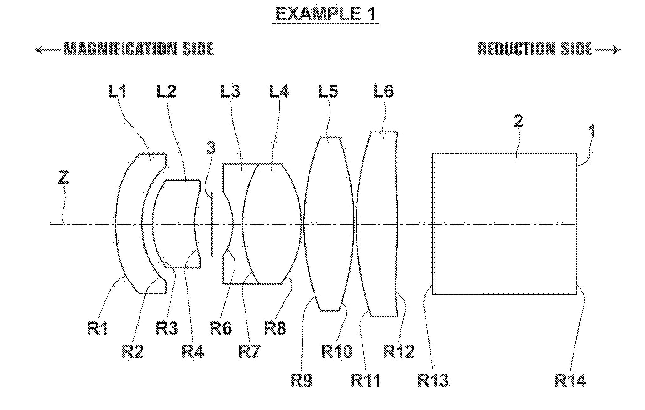
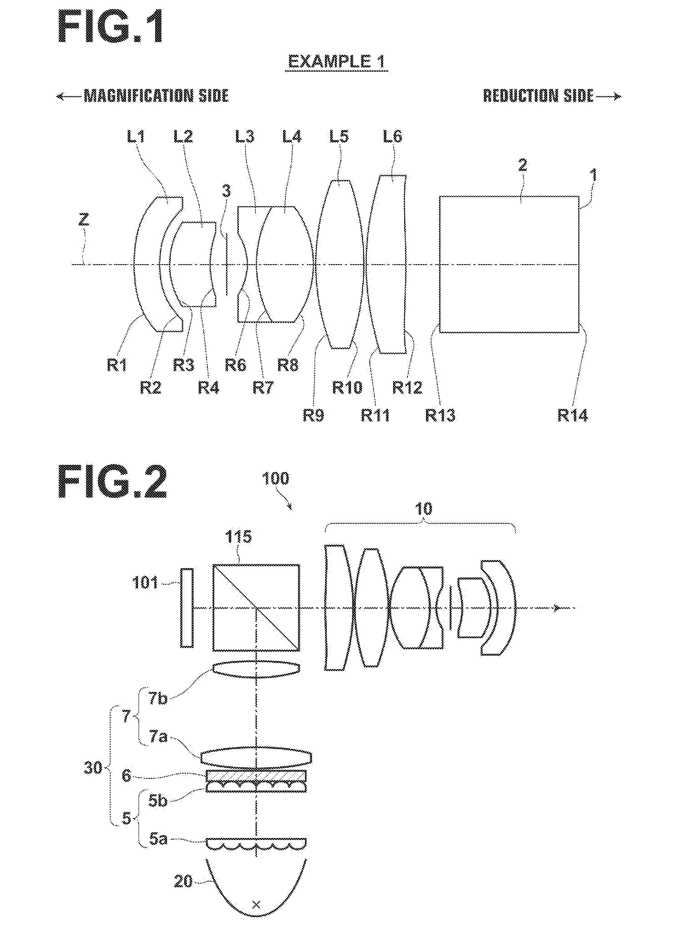
[0100]FIG. 1 illustrates the lens structure of a lens for projection in Example 1. Since a main explanation of FIG. 1 has been described already, a part of the explanation will be omitted here.

[0101]The structure of the lens for projection in Example 1 will be outlined. The lens for projection in Example 1 consists of six lenses of first lens L1 in negative meniscus shape with its concave surface facing a reduction side in a paraxial region, second lens L2, which is a positive meniscus lens with its concave surface facing the reduction side, third lens L3, which is a biconcave lens, fourth lens L4, which is a biconvex lens, fifth lens L5, which is a biconvex lens, and sixth lens L6 in biconvex shape in a paraxial region. Further, the lens for projection is structured so that the reduction side is telecentric. Third lens L3 and fourth lens L4 are cemented together. Both surfaces of first lens L1 and both surfaces of sixth lens L6 are aspherical. A stop 3 is arranged between second le...

example 2

[0112]FIG. 7 is a diagram illustrating the lens structure of a lens for projection in Example 2. The schematic structure of the lens for projection in Example 2 is similar to that of the lens for projection in Example 1, In Example 2, optical members 2a, 2b are used instead of the optical member 2 in Example 1. Table 3 and Table 4 show basic lens data and aspherical surface coefficients of the lens for projection in Example 2, respectively. FIG. 8, Sections A through D illustrate aberration diagrams of the lens for projection in Example 2.

TABLE 3EXAMPLE 2 BASIC LENS DATASiRiDiNdjνdj 0 (SCR)∞67.63 1*43.5040.151.491057.6 2*0.8840.05 30.6600.271.846723.8 41.3810.23 5 (St)∞0.20 6−0.4170.051.784726.3 71.3600.431.651658.5 8−0.7550.01 92.6420.341.772549.610−1.4960.0111*4.0540.221.491057.612*−2.6990.2613∞1.491.846723.814∞0.081.516364.115∞

TABLE 4EXAMPLE 2 ASPHERICAL SURFACE COEFFICIENTSURFACENUMBERKA3A4A5A6 11.00000.0000E+002.3142E+00−4.3386E+002.7167E+00 21.00000.0000E+002.1512E+00−1.7147E+...


PUM


Abstract

A lens for projection substantially consists of a negative first lens with its concave surface facing a reduction side, a positive second lens with its concave surface facing the reduction side, a negative third lens with its concave surface facing a magnification side, a positive fourth lens with its convex surface facing the reduction side, a positive fifth lens and a positive sixth lens in this order from the magnification side. The reduction side is telecentric. The following conditional formulas (1) and (2) about refractive power P4 of a reduction-side surface of the second lens, refractive power P5 of a magnification-side surface of the third lens, and focal length f of an entire system are satisfied:−3.0≦1 / (P4×f)≦−0.4   (1); and−2.0≦1 / (P5×f)≦−0.2   (2).

Description

CROSS-REFERENCE TO RELATED APPLICATIONS[0001]This application is a Continuation of PCT International Application No. PCT / JP2013 / 002560 filed on Apr. 16, 2013, which claims priority under 35 U.S.C. §119 (a) to Japanese Patent Application No. 2012-095342 filed on Apr. 19, 2012. Each of the above applications is hereby expressly incorporated by reference, in its entirety, into the present application.BACKGROUND OF THE INVENTION[0002]1. Field of the Invention[0003]The present invention relates to a lens for projection and a projection-type display apparatus. For example, the present invention relates to a lens for projection appropriately usable to magnify and project rays including video image information from a light valve onto a screen, and also so a projection-type display apparatus using the lens for projection.[0004]2. Description of the Related Art[0005]In recent years, a market for projection-type display apparatuses greatly expanded as personal computers became widely used. As ...

Claims


Application Information

Patent Timeline
Patent Type & Authority Applications(United States)
IPC IPC(8): G02B13/16H04N9/31G02B13/18
CPCG02B13/16H04N9/317G02B13/18G02B27/1026G02B9/62G02B13/0045
Inventor YAMAMOTO, CHIKARA
Owner FUJIFILM CORP
Why Eureka
Try Eureka