
System and method of non-destructive inspection with a visual scanning guide

a scanning guide and non-destructive technology, applied in the direction of mechanical measurement arrangements, mechanical roughness/irregularity measurements, instruments, etc., can solve the problems of poor reproducibility and reliability, difficult to follow the inspection scan line to ensure correct coverage of the inspected weld, and difficult to ensure the accuracy of inspection results. , to achieve the effect of reducing errors, ensuring correct coverage of welds, and simplifying analysis of resulting data

Active Publication Date: 2015-02-05
OLYMPUS AMERICA
View PDF12 Cites 22 Cited by
  • Summary
  • Abstract
  • Description
  • Claims
  • Application Information

AI Technical Summary

Benefits of technology

The visual scan guide system uses a 3D camera to track the position and orientation of a probe in real-time. The system also includes partially see-through glasses that display information generated by a scan path control module. This allows users to see where the probe is located in relation to the desired scanning path. The system compensates for small positioning errors by modifying the beam formation to alleviate the error. The analysis of the resulting data is simplified, and a proper coverage of the weld can be proven.

Problems solved by technology

Inspection of complex parts by non-destructive technologies can be quite challenging as finding and sizing a flaw or defect heavily depends on probe positioning during inspection.
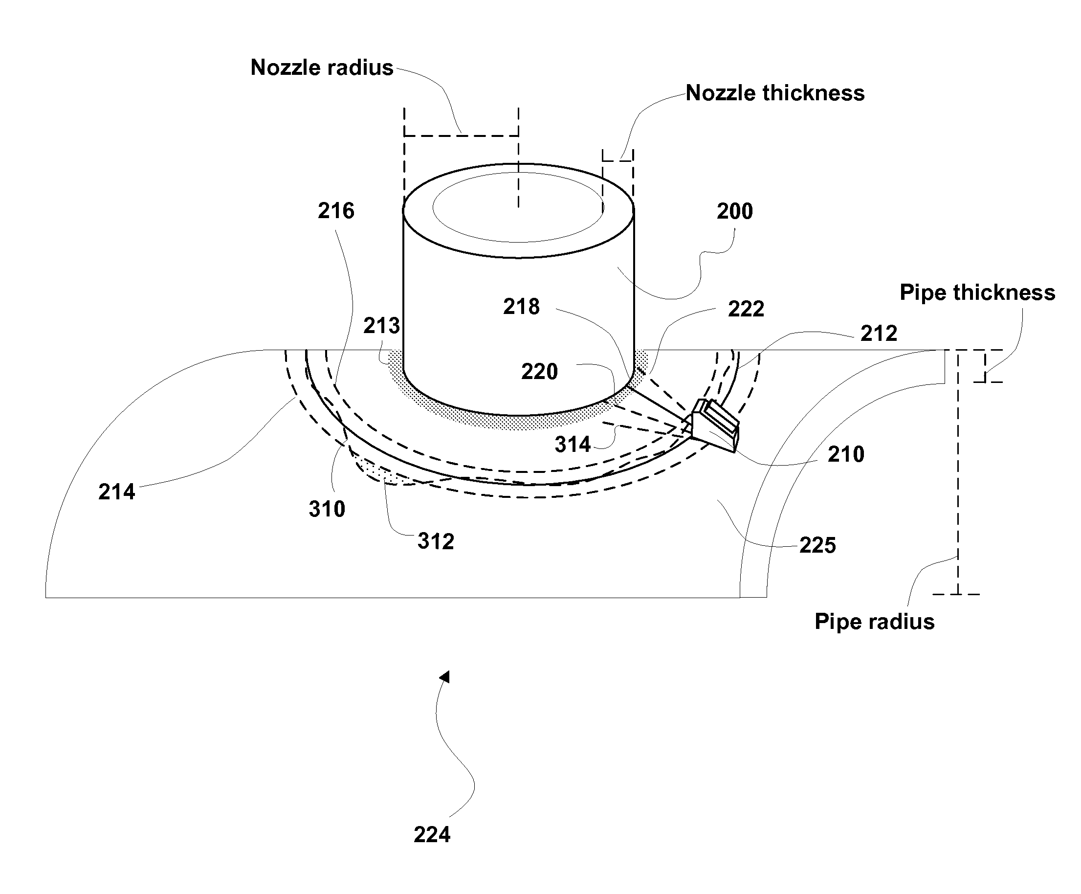
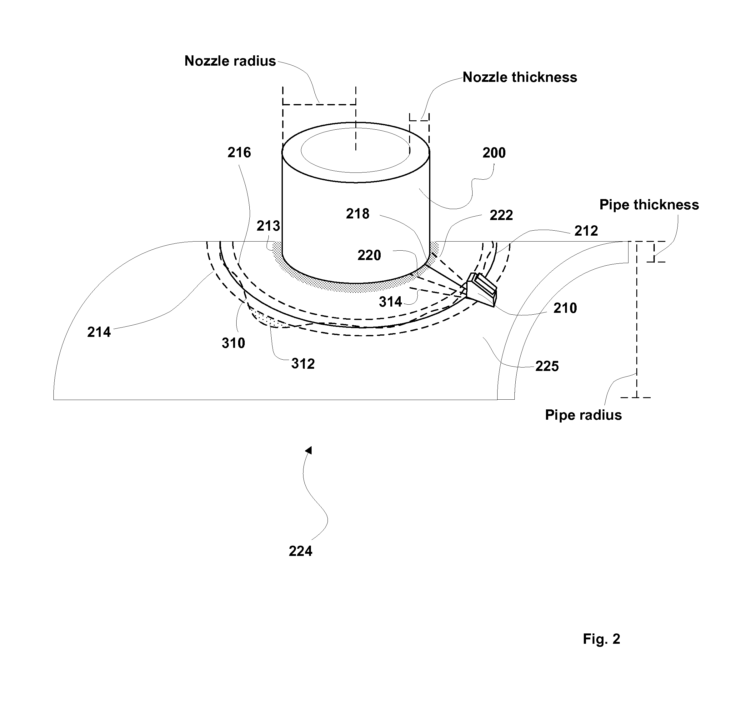
The complex shape of the nozzle, defined by the intersection of two cylinders, makes it difficult to follow the inspection scan line to ensure correct coverage of the inspected weld as defined by the scan plan.
Because such an inspection relies heavily on the user's experience, reproducibility and reliability is poor.
Under those conditions, it is also impossible to ensure the complete part was covered and to save meaningful data as the real position of the probe is unknown to the inspection system.
Such a scanner is an expensive alternative and is not suitable for all markets.
It also takes a lot of time to deploy, install and it lacks the manual versatility to better size a flaw or defect.
While these attempts solved some of the limitations of manual inspection (such as traceability and analysis) it has not been devised as an effective tool for guiding the probe position during the inspection.

Method used


Image

  • System and method of non-destructive inspection with a visual scanning guide
  • System and method of non-destructive inspection with a visual scanning guide
  • System and method of non-destructive inspection with a visual scanning guide

Examples


Embodiment Construction

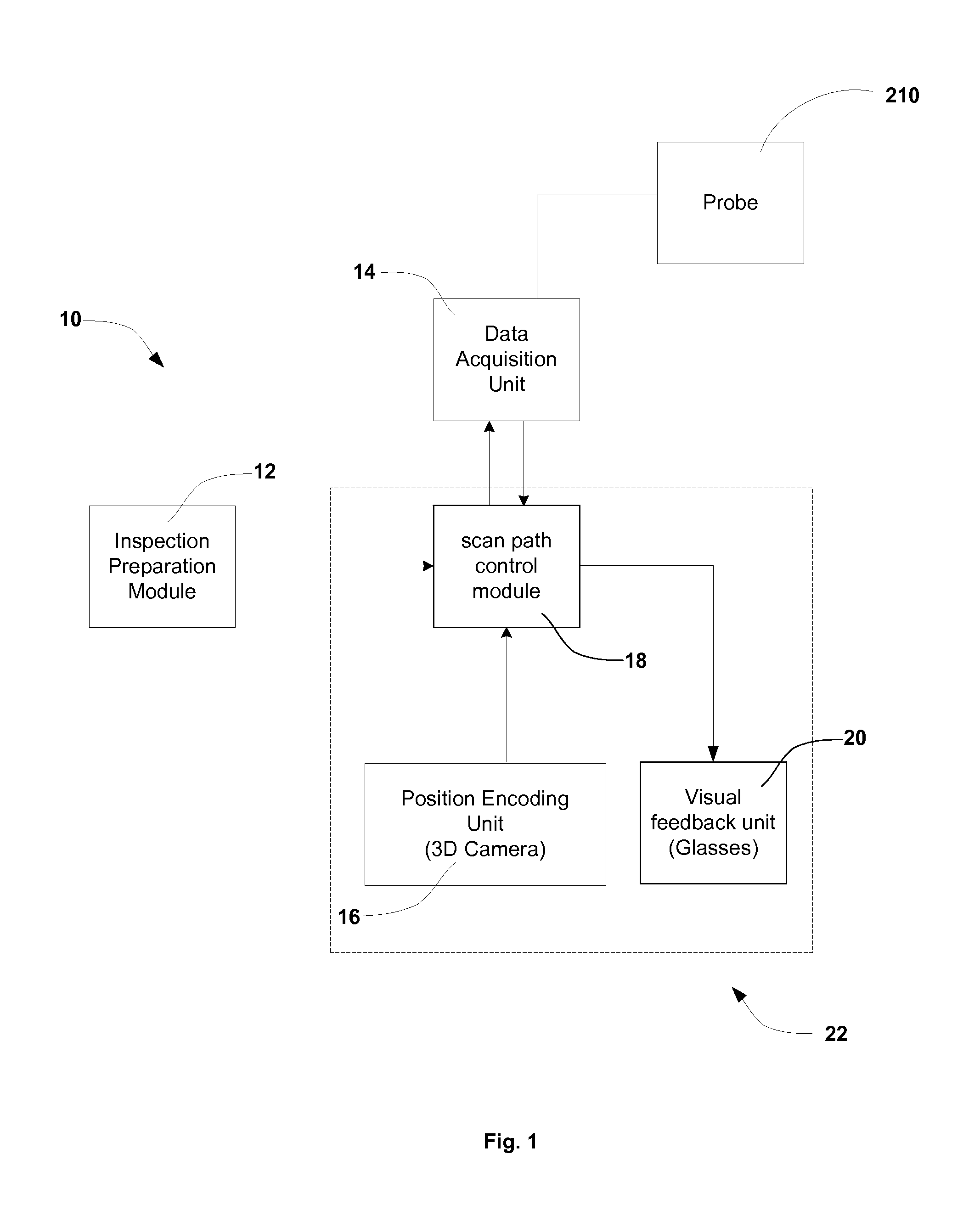
[0016]Referring to FIG. 1, the presently disclosed PA system 10 with visual guide 22 comprises a phased array probe 210, a data acquisition unit 14, an inspection preparation module 12, a position encoding unit 16, a scan path control module 18 and a visual feedback unit 20. Probe 210 and data acquisition unit 14 are all existing elements of a conventional phased array system and communicate information, such as inspection signals and operational commands, among each other. Added to the conventional PA system is a visual guide unit 22 (Details are shown in FIGS. 2 and 3) which is an assembly of a scan path control module 18, position encoding unit 16 and visual feedback unit 20.

[0017]Still referring to FIG. 1, scan path control module 18 is configured to perform the following functions:[0018]receiving inspection plan from inspection preparation module 12,[0019]updating data acquisition unit 14 with the correct configuration,[0020]retrieving position and orientation of the part and p...


PUM

PropertyMeasurementUnit
steering angleaaaaaaaaaa
ultrasonicaaaaaaaaaa
ultrasonic inspection instrumentaaaaaaaaaa

Abstract

Disclosed is an inspection device and method of guiding an inspection probe according to a predetermined inspection plan. The device is couple with a probe which is to be moved according to the inspection plan on the test object, the device including an inspection guide unit having a guide control unit, a position encoding such as a 3-D camera and visual feedback eyewear. The method including facilitating a virtual display of the inspection plan onto the visual feedback eyewear, moving the probe following the virtual display of the inspection plan, sensing sensed probe positions in real time of the inspection using the 3-D camera and validating the sensed probe position against the inspection plan using the control module. Then the information of the step of validating, such as those spots at which the probe is moved out of the tolerance of the inspection plan, is displayed on the feedback eyewear.

Description

FIELD OF THE INVENTION[0001]The present disclosure generally relates to a method and a system for conducting non-destructive testing / inspection (later as NDT / NDI), and more particular, it relates to guiding and informing an inspector in real time of an inspection path during a manual inspection of a test object.BACKGROUND OF THE INVENTION[0002]Inspection of complex parts by non-destructive technologies can be quite challenging as finding and sizing a flaw or defect heavily depends on probe positioning during inspection. In the exemplary embodiment of this invention, a nozzle weld phased array ultrasonic (PAUT) inspection is used. The exact position and number of required PAUT scan lines on particular nozzle geometry is defined by the scan plan, knowing that for weld inspection the whole weld zone must typically be completely covered by the various PAUT beams. The complex shape of the nozzle, defined by the intersection of two cylinders, makes it difficult to follow the inspection sc...

Claims


Application Information

Patent Timeline
Patent Type & Authority Applications(United States)
IPC IPC(8): G01N29/24
CPCG01N29/24G01N29/225G01N29/262G01N2291/2638G01N2291/267G01N27/902G01N29/043
Inventor LANGLOIS, PIERRELEPAGE, BENOITST-LAURENT, MARTINHABERMEHL, JASON
Owner OLYMPUS AMERICA
Learn More