System for Wireless Distribution of Power

a technology for wireless distribution and power distribution, applied in the direction of transformer/inductance coil/winding/connection, transformer/inductance circuit, etc., can solve problems such as efficiency impairmen

Active Publication Date: 2015-02-12
HOWARD KEITH MAXWELL
View PDF2 Cites 45 Cited by
  • Summary
  • Abstract
  • Description
  • Claims
  • Application Information

AI Technical Summary

Benefits of technology

[0065]This process secures the system from having ener

Problems solved by technology

(In practice any length may be used, however efficienc

Method used


Image

  • System for Wireless Distribution of Power
  • System for Wireless Distribution of Power
  • System for Wireless Distribution of Power

Examples


Embodiment Construction

[0073]This specification builds on the inventor's earlier filed Australian provisional patent application no 2012900054 filed 6 Jan. 2012 the disclosure of which including description, claims and drawings is incorporated herein by cross reference.

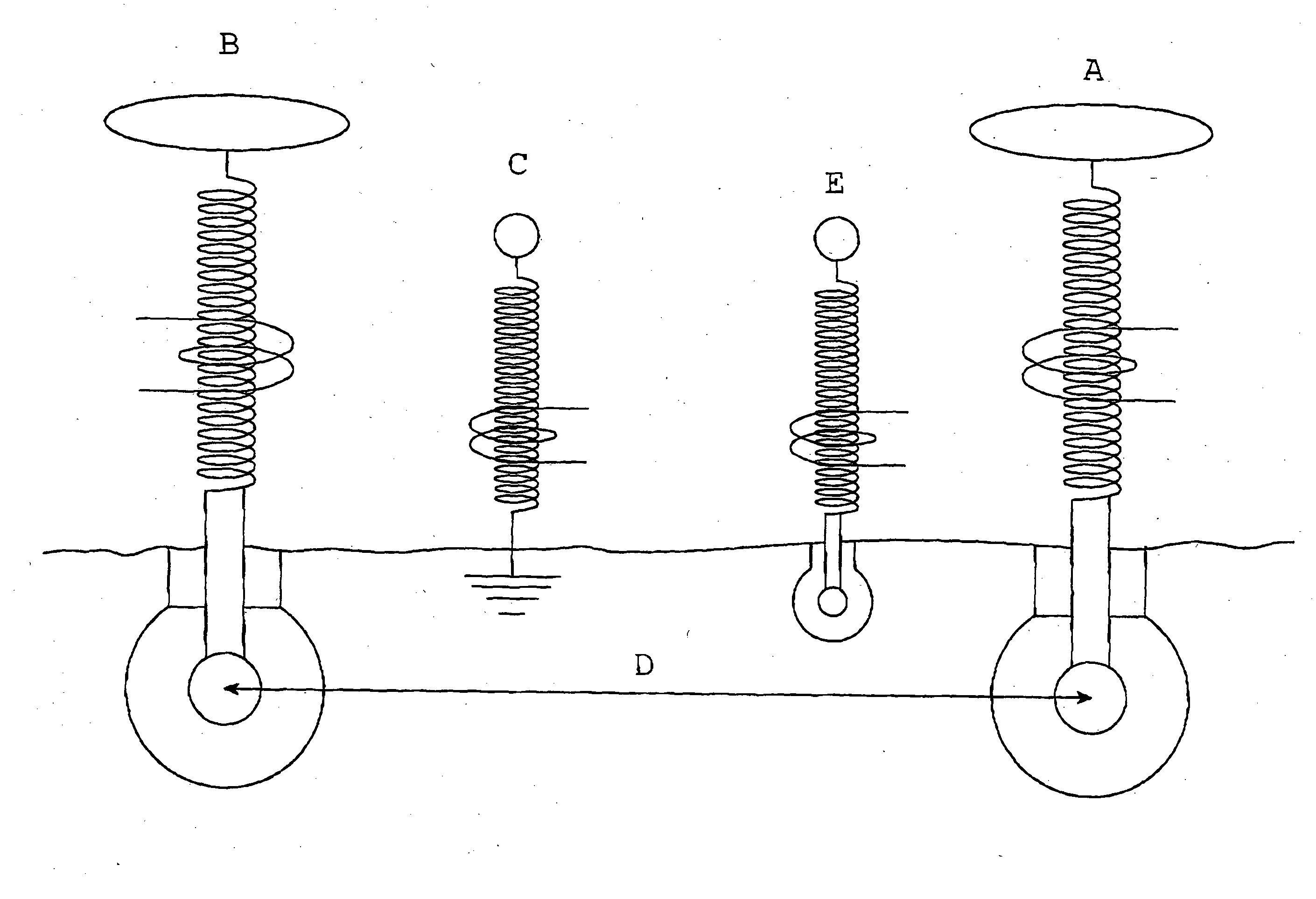
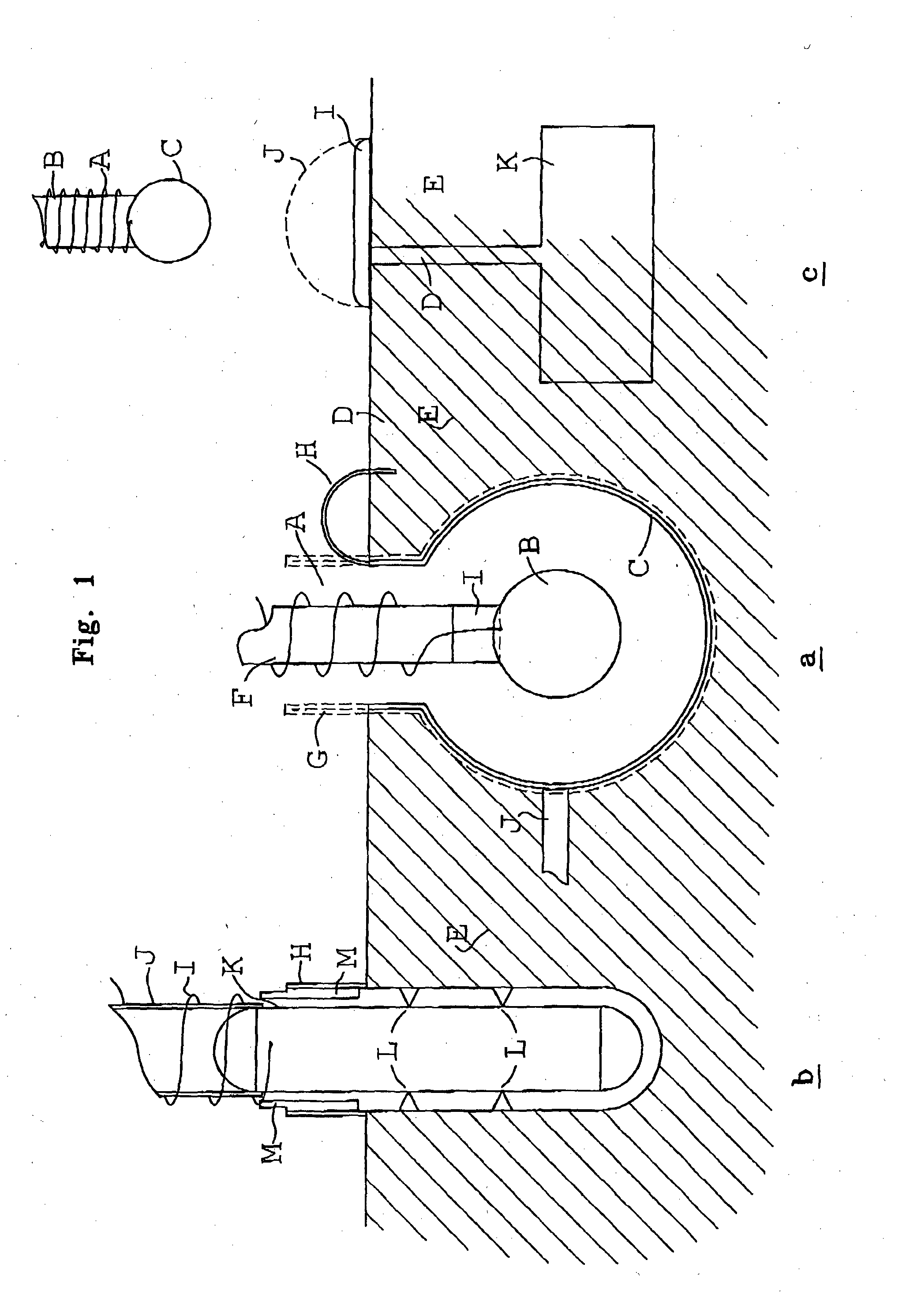
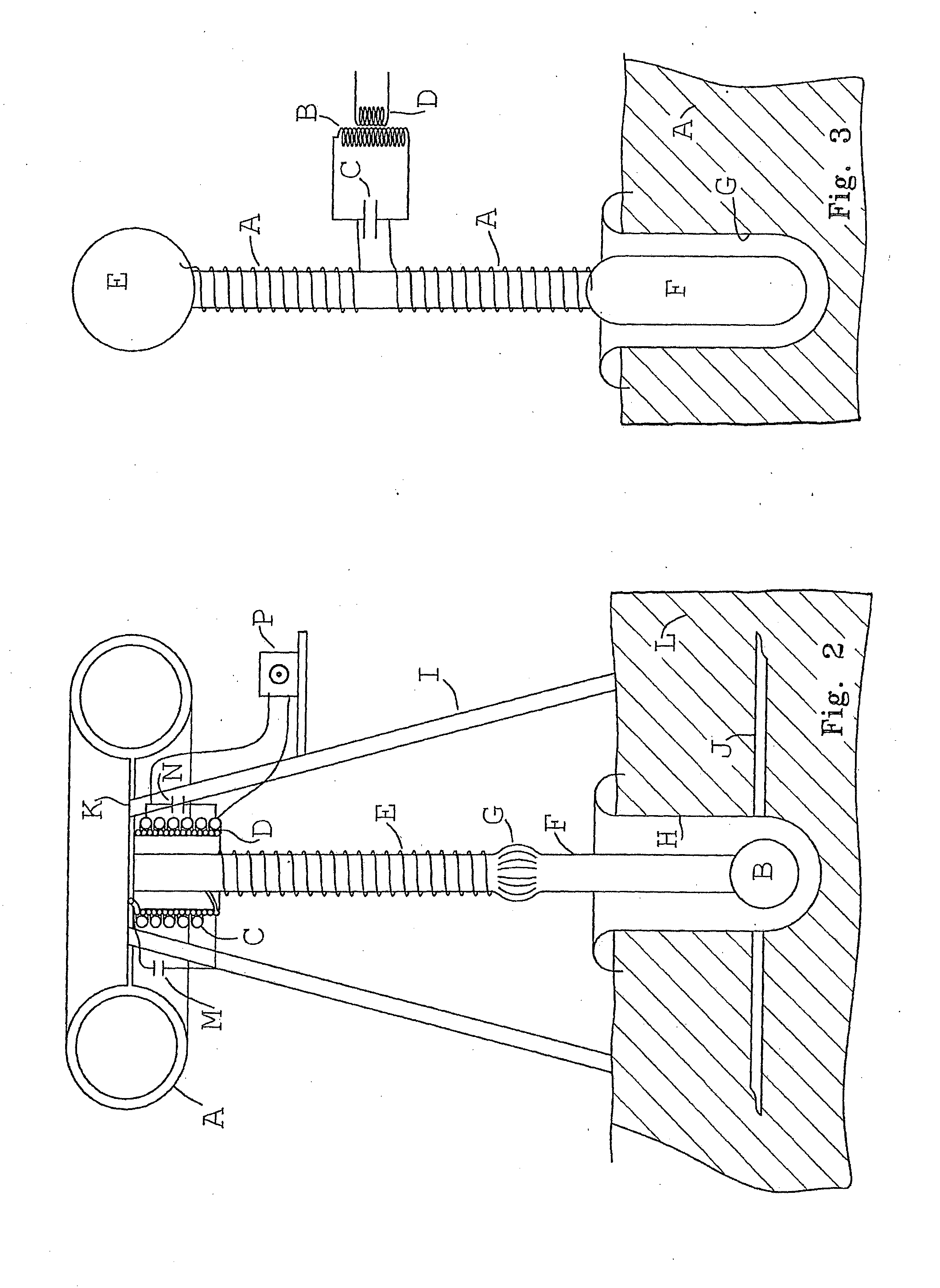
[0074]The preferred embodiment provides a means to connect to the earth with oscillating coils so that power transfer may take place between the earth and the power transmitter. An oscillating coil being a Tesla coil or magnifier or any other coil is set in motion using a generator or a DC pulse width driver or any other apparatus which causes the coil to gain frequency and also voltage. The highest voltage end is connected to a sphere or other suitable shaped object such as an ellipsoid which is placed inside a cavity which has been created in the ground and lined with conductive material with a good earth established with this lining. Both sides of the capacitor thus constructed should be made of an electrically conductive material. The c...


PUM


Abstract

A wireless power transmission system comprising a transmitting inverted Tesla Coil or Magnifier connected to the ground by its high voltage terminal using a capacitive earth connection and transmitting power through the ground to a subsequent receiving Tesla Coil or Magnifier being well earthed through a capacitive earth connection or conventional earth with the distance between the two earth connections of the transmitter and receiver plus the length of the coils in the transmitter and receiver forming a tuned length and the system thus composed being operated at a frequency that is an harmonic or close to an harmonic of the tuned length thus established.

Description

FIELD OF INVENTION[0001]The present invention relates to a method of earthing oscillating electric coils through a capacitive connection to the earth so that AC earth currents will be developed when the capacitive connection is oscillated with AC electrical energy. When two or more oscillating coils are used as transmitters then electrical currents flow between the capacitive connections to the earth of the coils facilitating wireless power transmission through the earth. Receivers may then utilize the electrical current to take power from the earth. This is facilitated by a new coil operating paradigm.BACKGROUND[0002]Any discussion of the prior art throughout the specification should in no way be considered as an admission that such prior art is widely known or forms part of common general knowledge in the field.[0003]Oscillating coils, particularly Tesla coils and Magnifiers have long since been used to produce high AC voltages and currents. A typical Tesla coil has an impedance o...

Claims


Application Information

Patent Timeline
IPC IPC(8): H02J17/00H01G4/002H01F27/28
CPCH02J17/00H01G4/002H01F27/28H01F38/14H02J50/12H02J50/23
Inventor HOWARD, KEITH MAXWELL
Owner HOWARD KEITH MAXWELL
Why Eureka
Try Eureka