Arrangement for Obtaining Reliable Anchoring of a Threaded Implant in a Bone

Inactive Publication Date: 2015-02-12
NOBEL BIOCARE SERVICES AG
View PDF3 Cites 11 Cited by
  • Summary
  • Abstract
  • Description
  • Claims
  • Application Information

AI Technical Summary

Benefits of technology

[0009]The problem with using cylindrical implants in cylindrical holes is that the thread which is in most cases created by the self-tapping tip of the implant is worn away as the implant is screwed in, and with this wearing the thread is widened, mainly at the inlet/mouth of the hole in the bone. This results in the implant having a slightly loose anchoring, especially in weak/soft bone, which means that the implant has a poor initial stability. When using conical implants with a conical preparation, one of the greatest problems is the development of heat which occurs during the conical preparation. Since a conical drill

Problems solved by technology

The problem with using cylindrical implants in cylindrical holes is that the thread which is in most cases created by the self-tapping tip of the implant is worn away as the implant is screwed in, and with this wearing the thread is widened, mainly at the inlet/mouth of the hole in the bone.
This results in the implant having a slightly loose anchoring, especially in weak/soft bone, which means that the implant has a poor initial stability.
When using conical implants with a conical preparation, one of the greatest problems is the development of heat which occurs during the conical preparation.
Since a conical drill cuts along the whole periphery, relatively great heat is generated, and this negative effect is amplified further by the fact that the cutting geometry of a conical drill becomes worse because a low surface pressure occurs at the periphery of the conical drill.
This means that the drill cannot cut proper chips but instead scrapes bone away, and this has a high heat generating effect.
This heat can damage the bone and can lead to the bone nearest the drilled hole dying.
This drastically reduces the possibilities of successful osteointegration.
This represents a relatively great risk since the implant is subjected to breaking stresses which me

Method used


Image

  • Arrangement for Obtaining Reliable Anchoring of a Threaded Implant in a Bone
  • Arrangement for Obtaining Reliable Anchoring of a Threaded Implant in a Bone
  • Arrangement for Obtaining Reliable Anchoring of a Threaded Implant in a Bone

Examples


Example

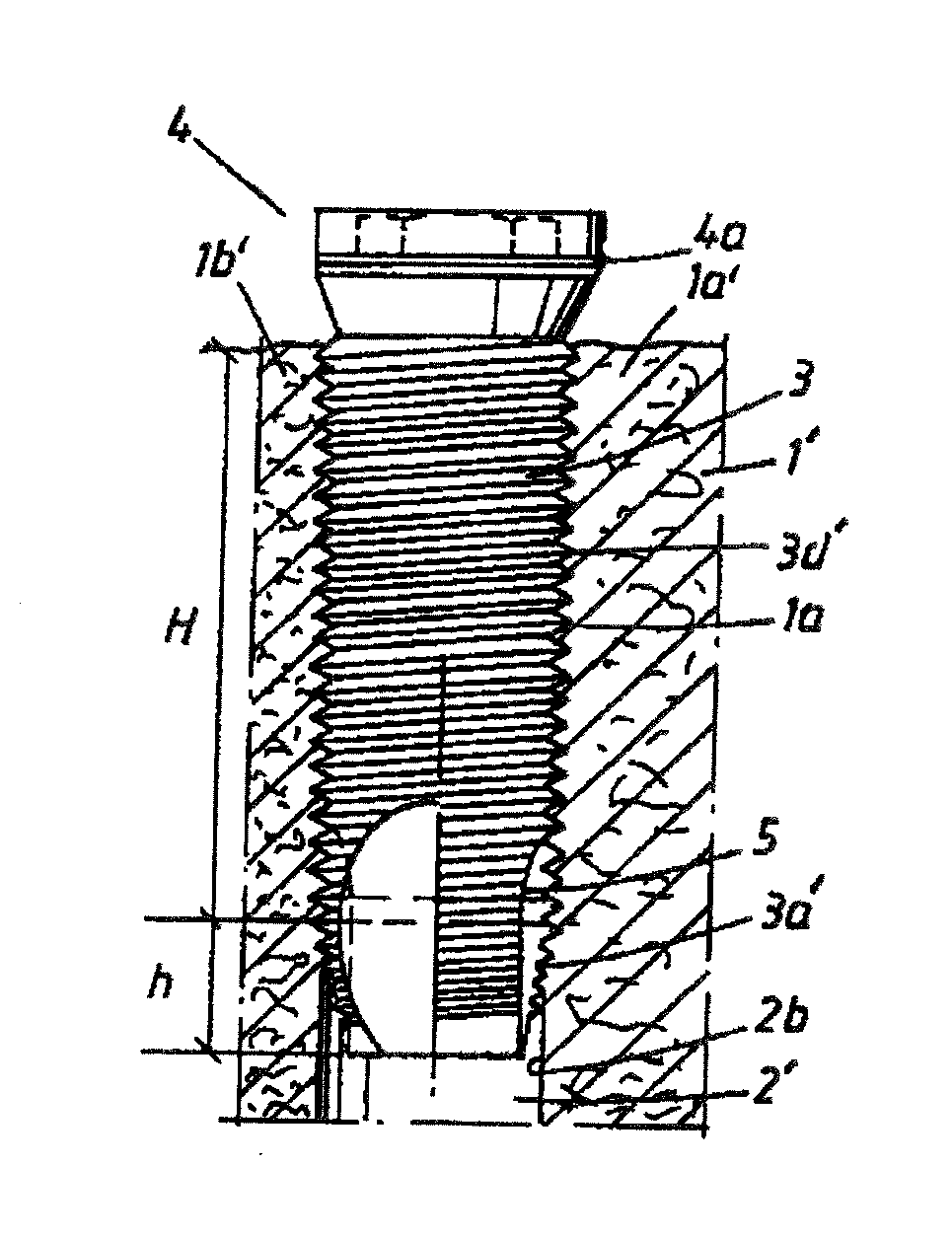
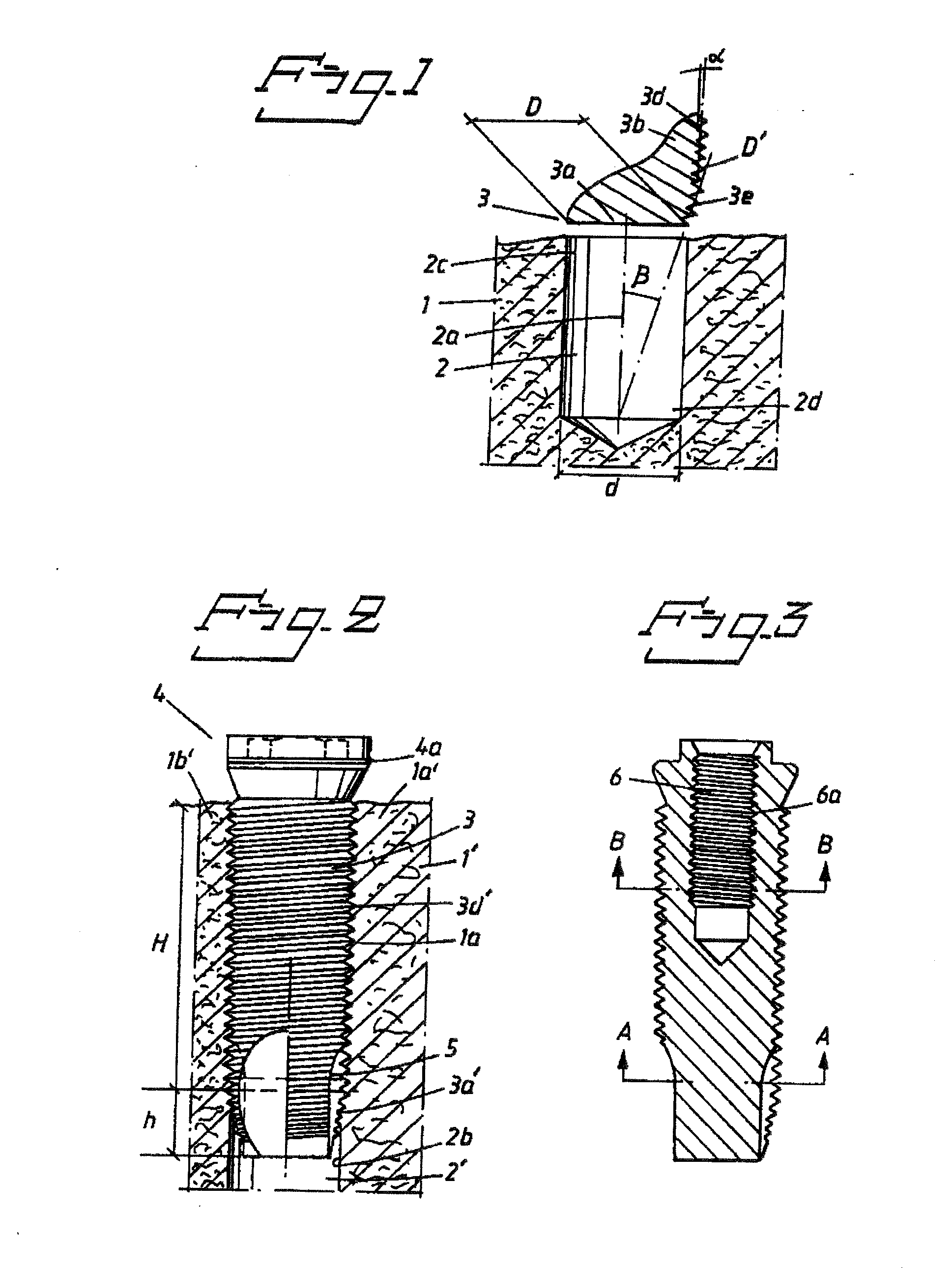
[0038]In FIG. 1, reference number 1 designates dentine. A circular hole 2 has been made in the dentine. The hole can be made in a manner known per se using equipment known per se. An implant with threads of, different conicities can be applied to the hole. Parts of the said implant are represented by parts of the free end 3 of the implant. The said free end has a tip part 3a which merges into a part 3b. The latter part has a thread 3d which has a slight conicity. Slight conicity is understood here as meaning conicities in which an angle of inclination α is of the order of 1° in relation to a vertical axis 2a of the hole 2 or an axis parallel to this axis. The tip 3a is provided with a thread 3e which is arranged with a conicity which gives an angle β of the order of 10°. The entry surface or entry part of the tip 3a has a diameter D′ which essentially corresponds to the diameter d of the hole or slightly exceeds the said diameter d. The hole diameter d can also be chosen as a functi...


PUM


Abstract

In an arrangement for obtaining reliable anchoring of a threaded implant in dentine, a hole is made in the bone substance. In the side wall of the hole it is possible to establish an internal threading which can cooperate with an external threading on the implant. The implant threading is arranged to force the bone substance out in essentially radial directions as a function of the extent to which the implant is screwed into the hole. The threading is arranged to effect greater forcing out of the bone substance at the outer parts of the hole than at the inner parts of the hole. The degree of forcing out is adapted in relation to the softness of the bone in order to achieve the reliable anchoring. Along at least part of the longitudinal direction of the implant, the implant threading can be given a non-circular configuration for the purpose of obtaining improved rotational stability in soft/weak bone.

Description

CROSS REFERENCE TO RELATED APPLICATIONS[0001]This application is a continuation application of U.S. patent application Ser. No. 09 / 509,869 filed Jun. 15, 2000, which is, in turn, a continuation of international patent application PCT / SE98 / 01982, filed Nov. 3, 1998, designating the United States and claiming priority from Swedish application 9704112-3, filed Nov. 11, 1997, and the entire content of both applications is incorporated herein by reference.FIELD OF THE INVENTION[0002]The present invention relates to an arrangement for obtaining reliable anchoring of a threaded implant in bone, preferably dentine, in the human body. The bone in question is in this case provided with a hole in whose side wall it is possible to establish an internal threading which can cooperate with an external threading on the implant for reliable anchoring and healing-in of the implant in the bone substance.BACKGROUND OF THE INVENTION[0003]Implants with threads, for example self-tapping threads, for inser...

Claims


Application Information

Patent Timeline
IPC IPC(8): A61C8/00A61F2/28A61L27/00
CPCA61C8/0025A61C8/0022A61C8/005A61C8/0068A61C8/0089
Inventor CARLSSON, LENNARTENGMAN, FREDRIKFROMELL, ROGERJOERNEUS, LARS
Owner NOBEL BIOCARE SERVICES AG
Why Eureka
Try Eureka