Electric Vehicle Refueling System

a technology for electric vehicles and refueling systems, applied in the direction of electric/fluid circuits, metal sawing equipment, climate sustainability, etc., can solve the problems of prohibitive 50% of the purchase price of a new battery powered electric vehicle, the cost of a complete set of rechargeable batteries, etc., and achieves simple structure, high commercial potential, and easy sequential conveying

Inactive Publication Date: 2015-02-19
BATTERY FUELING
View PDF0 Cites 21 Cited by
  • Summary
  • Abstract
  • Description
  • Claims
  • Application Information

AI Technical Summary

Benefits of technology

[0030]Practical application of this primary object of the invention can dispel the long held rigid belief that a battery powered electric vehicle can only have a large, heavy, cuboid, cumbersome, prohibitively expensive and inaccessible battery block installed.
[0033]The primary object of the invention, to treat a single small-volume rechargeable Cell-Module (100) and (500) as the smallest unit of ‘metered-for-payment’ motive power input energy, is used in the invention to provide practical means for a Cell-Module (100) and (500) to be treated as a Flow-Unit, just as small volumes of fossil fuel are conventionally treated as flow-units, so that, for example, a plurality of small-volume Cell-Modules (100) and (500) can be easily sequentially conveyed though a small diameter tube or a hollow enclosure, as can a small volume of sequentially conveyed liquid fossil fuel.
[0034]It follows therefore, that the invention has great commercial potential for electric vehicle manufacturers to provide Cell-Module Chambers (15) of extremely complex form, as well as simple form, that can readily fit around other essential vehicle components within a Vehicle (1).
[0035]The invention can also provide additional commercial value to electric vehicle manufactures, not least where the 50% financial burden of battery ownership may be removed from a new electric vehicle's purchase price and placed with a motive power energy replenishment provider, who may commercially amortise their investment, by way of the continuous cyclical dispensing of Cell-Modules (100) and (500), via the System (200) of the invention, in a similar manner that has been conventionally successfully amortised by non-cyclical Oil Corporations via dispensing bowsers, for more than a century.

Problems solved by technology

Also, the cost of a complete set of rechargeable batteries, that replicates the equivalent of a full tank of fossil fuel, can represent a prohibitive 50% of a new battery powered electric vehicle's purchase price.

Method used


Image

  • Electric Vehicle Refueling System
  • Electric Vehicle Refueling System
  • Electric Vehicle Refueling System

Examples


first embodiments

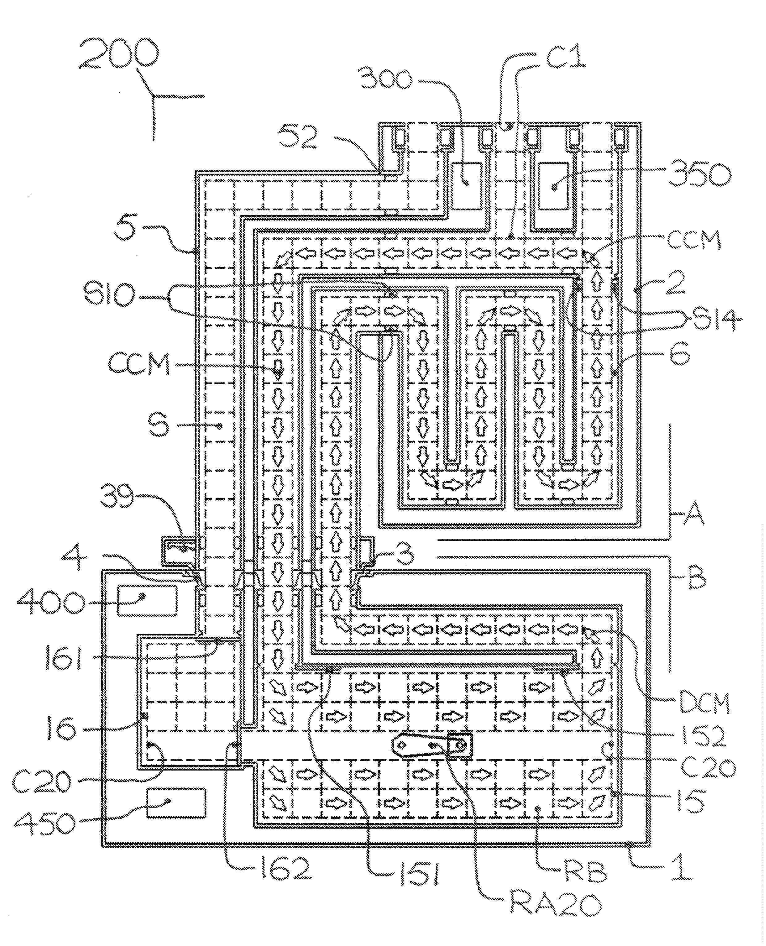
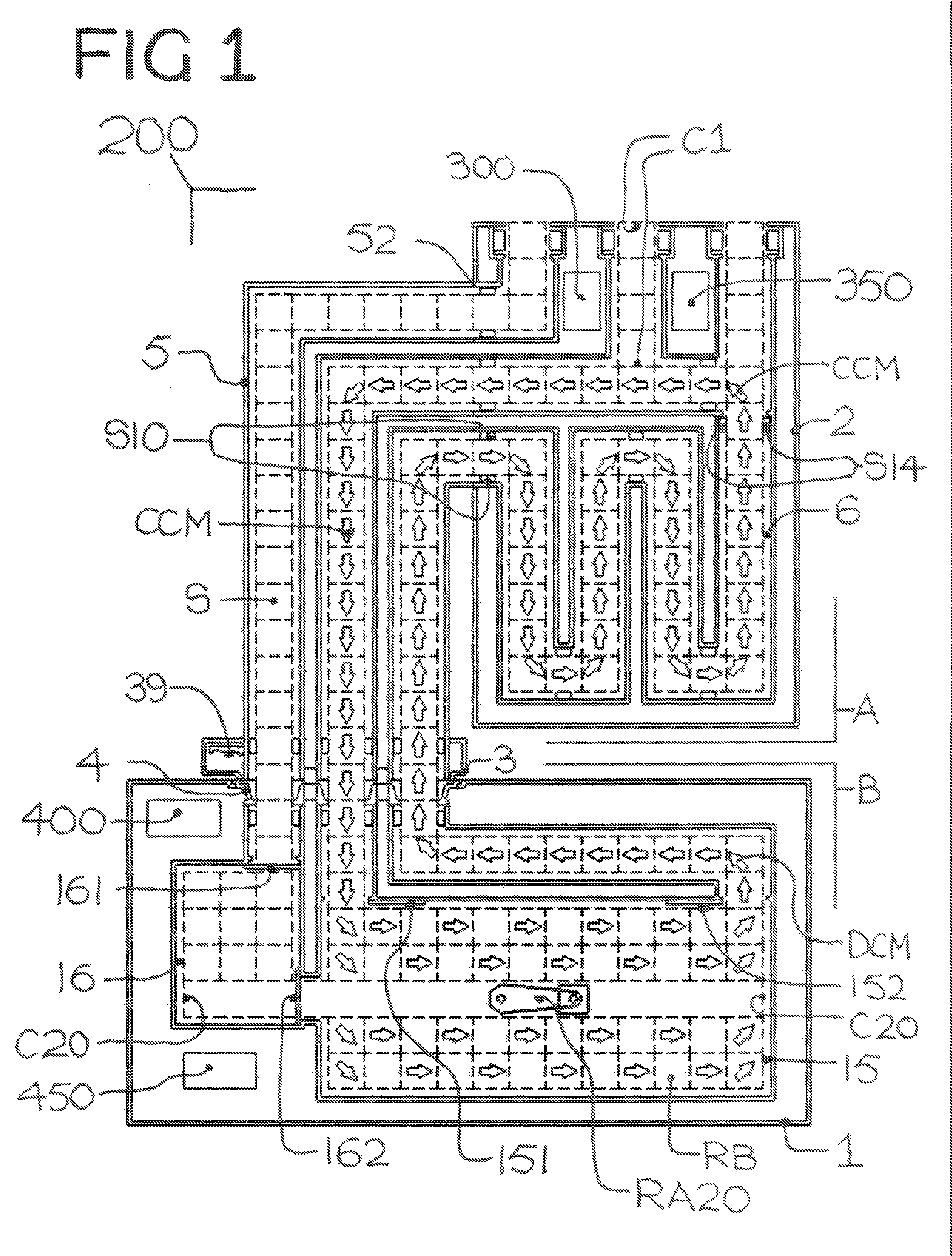
[0140]FIG. 1 is a general schematic down-view, for defining in introductory terms, the First Embodiments of an Enclosed Computer-Controlled Cyclical Through-Flow Sequential Conveyor System (200), for the sequential computer-controlled conveyance of a very large number of identical individual small-volume rechargeable Cell-Modules (100) through and within an Enclosed System.

[0141]In this drawing, no Cell-Modules (100) are actually shown.

[0142]Instead, the physical extremities of each individual Cell-Module (100), that may be disposed within a System (200), is schematically disclosed by the use of four broken straight lines that together form a bounding Square (S).

[0143]Each Cell-Module's sequentially conveyed position within a simple version of an Enclosed System (200) is thus illustrated by the use of a sequentially positioned Flow-Direction-Arrow within each bounding Square (S).

[0144]An Enclosed System (200) generally comprises a Stationary Part (A) that is shown temporarily but se...

second embodiments

[0403]In the First Embodiment disclosures, means were provided for recharging Depleted Cell-Modules (DCM) within the Casing of a Cell-Module dispensing Bowser (2), prior to conveying them directly from the Bowser, as freshly Charged Cell-Modules (CCM) towards another Vehicle (1), for ‘metered-for-payment’ recycled use therein.

[0404]In a practical application of such a First Embodiment, the Bowser casing would need to be physically enormous, for containing very large numbers of recharging Cell-Modules, especially if the Bowser was being visited by a continuous number of sequential Vehicles, all needing substantial Cell-Module replenishment.

[0405]For the Second Embodiment disclosures, means are specifically not provided for recharging Depleted Cell-Modules (DCM) within the Casing of a Bowser (2).

[0406]Instead, Depleted Cell-Modules that have just been removed from an adjacently parked Vehicle (1) would be conveyed straight through the casing of a Second Embodiment Bowser (2), for then...

third embodiments

[0471]FIG. 22 represents, in its most whittled down visual form, the simplest schematic disclosures for Third Embodiments of an Enclosed Cyclical System (200).

[0472]All the different interacting Conveyors that were previously disclosed for the Stationary part (A), have been reduced to a single semi-circular Conveyor (CB) of endless belt form, that has been installed within the Casing of a simple Cell-Module dispensing Bowser (2).

[0473]Similarly, all the different interacting Conveyors that were previously disclosed for the Movable part (B), have also been reduced to a single semi-circular Conveyor (CV) of endless belt form, that has been installed within the Bodywork of a simple Cell-Module powered electric Vehicle (1).

[0474]The drawing also discloses that when the simple Bowser (2) is temporarily adjoined the simple Vehicle (1), the semi-circular Conveyor (CB) is shown as an arch and the semi-circular Conveyor (CV) is shown as a bowl.

[0475]Eight Cell-Modules (100) are each depicted...


PUM

PropertyMeasurementUnit
sizeaaaaaaaaaa
dead weightaaaaaaaaaa

Abstract

An enclosed two-part computer controlled cyclical and sequential through-flow conveying, usage and metering System (200) is disclosed, for use in the electric vehicle motive power provision industries, for said two-part enclosed System to sequentially convey small-volume rechargeable Cell-Modules by sequential conveyor-means in a metered through-flow sequential conveying manner within said two-part System wherein the first part is a Stationary Part that includes a specially manufactured Cell-Module dispensing Bowser and a specially manufactured Cell-Module Charging-Bay and wherein the second part is a Movable Part that includes a specially manufactured or specially adapted Cell-Module powered electric Vehicle having a specially manufactured Cell-Module Chamber installed within.A Nozzle (3) and a Portal (4) respectively provide means for the Stationary Part and the Movable Part to exchange a choosable plurality of small-volume rechargeable Cell-Modules (100) and (500).A System (200) provides a succinct fully enclosed matingly-co-operative interconnection means for the System (200) to sequentially dispense Charged Cell-Modules and remove depleted Cell-Modules. The System also removes faulty Cell-Modules and if necessary extinguishes, and isolates for fire safety purposes, over-heating, deformed, or ignited Cell-Modules.The invention provides means that parallel, mimic or improve upon the metered bowser dispensing manner by which a choosable sequential plurality of small volumes of fossil fuel are sequentially delivered to a conventional fossil fuel vehicle by a dispensing bowser at a conventional fuel Service Station facility. The invention also provides optional means for Cell-Modules to be recharged in situ by use of a specially manufactured charger.

Description

CROSS-REFERENCE TO RELATED APPLICATIONS[0001]Not ApplicableSTATEMENT REGARDING FEDERALLY SPONSORED RESEARCH OR DEVELOPMENT[0002]Not ApplicableREFERENCE TO SEQUENCE LISTING, A TABLE, OR A COMPUTER PROGRAM LISTING COMPACT DISK APPENDIX[0003]Not ApplicableBACKGROUND OF THE INVENTION[0004]For more than a century, the different developments for fossil fuel powered vehicles have been supported by parallel developments for fossil fuel replenishment needs.[0005]Today, drivers of many types of fossil fuel powered vehicles can readily obtain choosable pluralities of precisely metered sequential small volumes of fossil fuel, by the use of the same globally established, globally understood and globally accepted apparatus; the roadside Service Station bowser, also known as the forecourt replenishment bowser.[0006]The driver of a fossil fuel powered vehicle is able to drive into a roadside Service Station, almost anywhere in the world, park his vehicle adjacent a forecourt dispensing bowser, and ...

Claims


Application Information

Patent Timeline
Patent Type & Authority Applications(United States)
IPC IPC(8): B60S5/06
CPCB60S5/06B60L3/0046B60L3/04B60L3/12B60L2240/547B60L2240/549B60L2250/10B60L2250/16B60L50/52B60L53/30B60L53/305B60L53/80B60L58/14B60L58/21Y02T10/70Y02T10/7072Y02T90/12Y02T90/16Y02T90/14
Inventor TAIT, GORDON ROY
Owner BATTERY FUELING
Why Eureka
Try Eureka