
Steam reformer furnace, and method for the same

a technology of reformer furnace and steam furnace, which is applied in the direction of chemical/physical/physical-chemical processes, chemical apparatus and processes, organic chemistry, etc., can solve the problems of reducing the efficiency of the furnace, so as to reduce the fuel consumption and co2-emissions, reduce the cost of construction and maintenance, and reduce the effect of fuel consumption

Active Publication Date: 2015-02-19
STAMICARBON BV
View PDF3 Cites 9 Cited by
  • Summary
  • Abstract
  • Description
  • Claims
  • Application Information

AI Technical Summary

Benefits of technology

The present invention is a compact, economical to manufacture, maintain, and operate, and offers reduced fuel consumption and CO2-emissions compared to conventional reformer furnaces. The triple conduit assembly of the furnace has a structurally simple, yet highly efficient double, full-length counter-current heat exchanger that allows for a continuous heat flow during operation, which in turn leads to reduced fuel consumption and CO2-emissions. The design is also advantageous because it simplifies the furnace's construction, reduces its maintenance costs, and avoids the need for early maintenance. Additionally, the patent describes a simplified design of the furnace that allows for a more compact arrangement of the burners and reaction conduit.

Problems solved by technology

A notorious problem with known reformer furnaces is that both the product gas and the flue gas may exit at relatively high temperatures.
These reformer furnace designs, however, appear to leave room for efficiency improvements.
Furthermore, they may typically be relatively complex and sizeable, making them costly to construct and maintain.

Method used


Image

  • Steam reformer furnace, and method for the same
  • Steam reformer furnace, and method for the same
  • Steam reformer furnace, and method for the same

Examples


Embodiment Construction

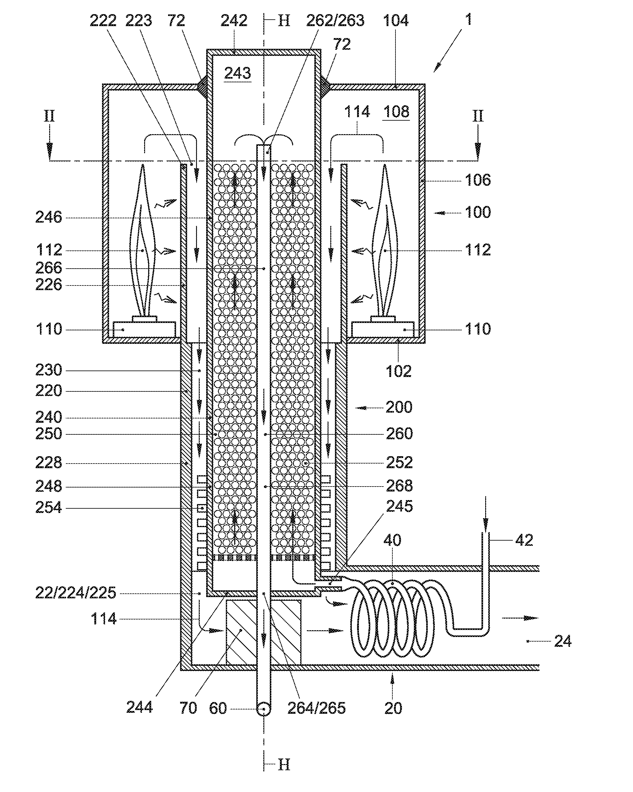
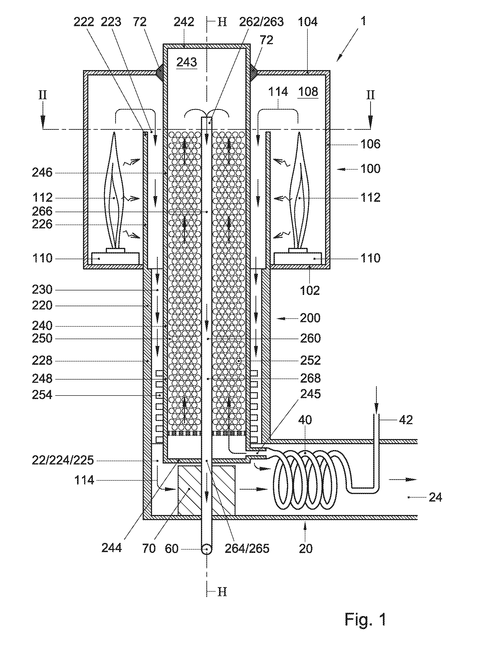
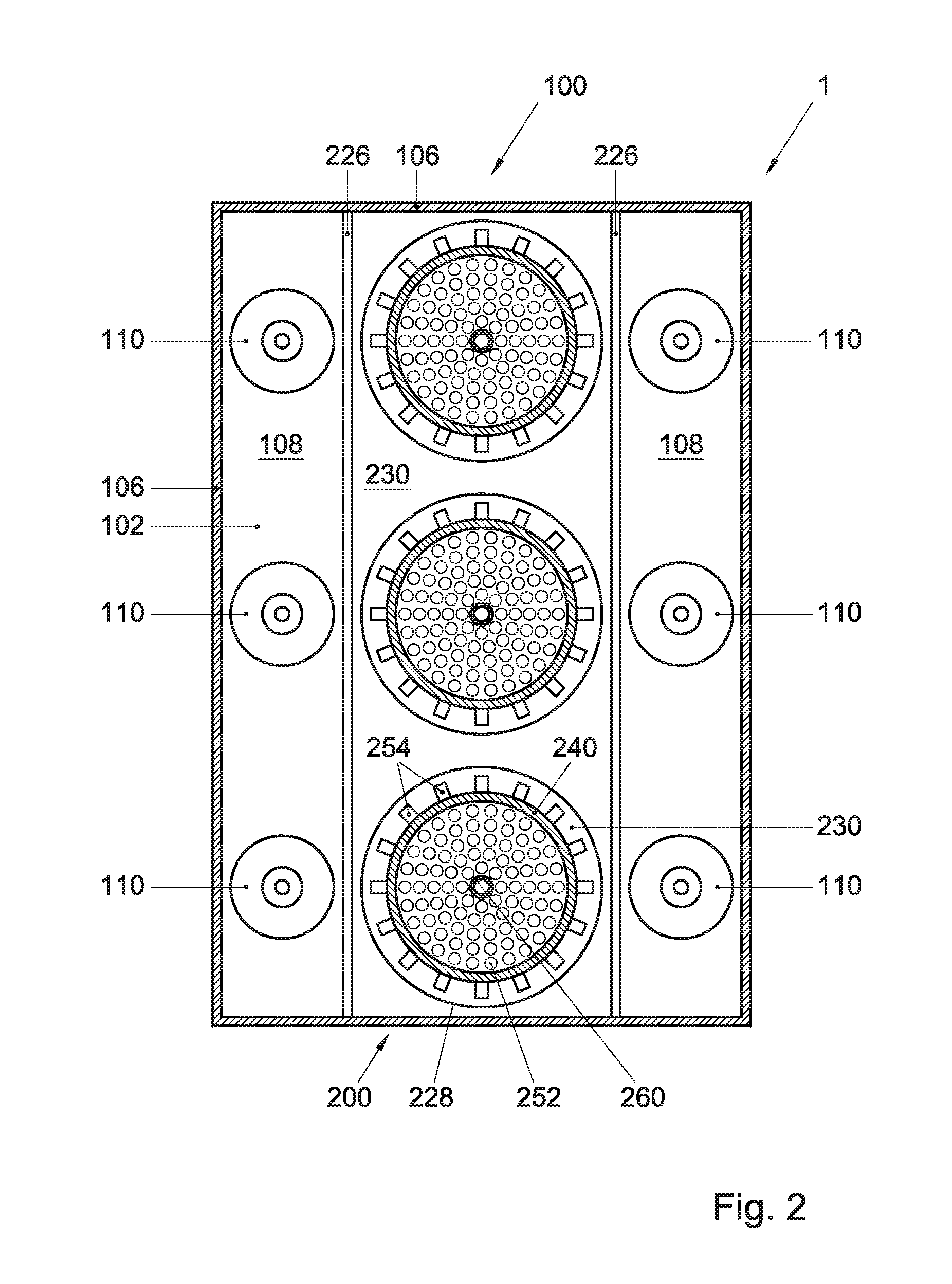
[0015]FIG. 1 is a schematic cross-sectional side view of an exemplary reformer furnace 1 according to the present invention. FIG. 2 is a cross-sectional top view of the reformer furnace 1 shown in FIG. 1, taken along line II-II indicated therein. Hereafter, the reformer furnace 1 according to the present invention will be described in general terms, where appropriate with reference to the exemplary embodiment shown in FIGS. 1 and 2.

[0016]The reformer furnace 1 may comprise at least one elongate triple conduit assembly 200. The triple conduit assembly 200 may include a preferably vertically oriented flue gas conduit 220 that encloses or surrounds a reaction conduit 240, which reaction conduit in turn encloses a product gas conduit 260. The three conduits 220, 240, 260 may have an approximately same length, typically in the range of about 10±2 meters (which is about 10-20% shorter than traditional catalyst tubes), and extend along a common vertical axis H. At their ends the conduits 2...


PUM


Abstract

A reformer furnace (1), comprising: at least one triple conduit assembly (200), including a flue gas conduit (220) enclosing a reaction conduit (240) enclosing a product gas conduit (260), wherein: the reaction conduit (240) extends between a lower end (244) defining a reaction gas inlet (245), and a closed upper end (242); the product gas conduit (260) extends between an upper end (262) defining a product gas inlet (263), and a lower end (264) defining a product gas outlet (265); the flue gas conduit (220) extends between an upper end (222) defining a flue gas inlet (223), and a lower end (224) defining a flue gas outlet (225); and an annulus (250) between the reaction conduit (240) and the product gas conduit (260) comprises a catalyst (252); a combustion chamber (100) that encloses an approximate upper half (226, 246, 266) of the at least one triple conduit assembly (200) while an approximate lower half (228, 248, 268) thereof resides outside of and below the combustion chamber, and that includes at least one burner (110), disposed inside of the combustion chamber and outside of the flue gas conduit (220), such that the approximate upper half (226) of the flue gas conduit substantially shields the reaction conduit (240) from direct burner flame heat radiation and impingement.

Description

FIELD OF THE INVENTION[0001]The present invention relates to a reformer furnace for steam reforming a hydrocarbon feedstock, and to a method for the same.BACKGROUND[0002]Steam reforming is a chemical process by which a hydrocarbon feedstock reacts with steam to form a product gas mixture comprising hydrogen and carbon oxides. The reaction, which is strongly endothermic, takes place in a reactor called a reformer furnace.[0003]The reformer furnace may typically include a tubular reaction vessel containing a steam reforming catalyst through which the reactant mixture of hydrocarbons and steam (also called: mixed-feed) is flown. The reaction vessel may be wholly or partly disposed inside a combustion chamber of the reformer furnace fitted with a number of burners that combust fuel to produce the heat necessary to sustain the endothermic reforming reaction inside the reaction vessel. Heat may be transferred to the reaction vessel by radiant heat directly from the burner flames, or by co...

Claims


Application Information

Patent Timeline
IPC IPC(8): C01B3/38B01J7/00
CPCC01B3/38B01J2219/18B01J7/00C01B3/384C01B2203/0233C01B2203/0811C01B2203/1235B01J8/0257B01J2208/00221B01J2208/00309B01J2208/00504B01J2208/0053
Inventor VOLPI, PAOLAMORICO, BARBARAMOSCA, LORENAGUAZZOTTI, CRISTINAPROSPERI, FABIOIAQUANIELLO, GAETANO
Owner STAMICARBON BV
Learn More