Motor vehicle with a device for reducing an air stream flow into a wheel house

a technology for motor vehicles and air streams, applied in the direction of vehicle bodies, monocoque constructions, superstructure subunits, etc., can solve the problems of disturbed air flowing around the vehicle, achieve the effect of reducing the flow cross section of air, improving the aerodynamics of the motor vehicle, and reducing volumetric flow

Active Publication Date: 2015-02-19
DR ING H C F PORSCHE AG
View PDF3 Cites 9 Cited by
  • Summary
  • Abstract
  • Description
  • Claims
  • Application Information

AI Technical Summary

Benefits of technology

[0010]The invention relates to a device that is connected to a part of an underbody panel of a motor vehicle at a side of the underbody panel facing the wheel house. The device is pivotable about an axis that is parallel to a longitudinal axis of the motor vehicle. As a result, the device reduces the flow cross section of the air into the wheel house in the region of the lower side of the wheel house while the vehicle is moving. Only a significantly reduced volumetric flow of air can therefore flow into the wheel house from below. Covering part of the wheel house from below improves aerodynamics of the motor vehicle. Air coming from the underbody can flow up into the wheel house only with a significantly reduced volumetric flow. Thus, a significantly lower aerodynamic drag of the motor vehicle and a lower lift of the motor vehicle in the region of the vehicle axle assigned to the wheel house are produced in comparison to a free flow possibility from below into the wheel house without the device.
[0011]The pivot axis is a longitudinal axis of the motor vehicle. Thus, the device of the invention can pivot during compression and rebound of the wheel in the wheel house and is not damaged by a chassis component that receives the wheel.
[0012]The device preferably is formed by an enlargement of the underbody panel into the wheel house. This design permits a structurally simple formation of the arrangement of underbody panel and device. The underbody panel can thus be enlarged only by the region taken up by the device.
[0014]The device can be plate-like and hence can be produced in a particularly simple manner, for example by shaping a plastics part. The device and the underbody panel may be produced in a common production process.
[0017]The invention effectively enlarges an underbody panel of a motor vehicle in the direction of the wheel house. This enlargement of the underbody panel is achieved by the device and reduces the flow of air into the wheel house while the vehicle is moving, and improves the aerodynamics of the motor vehicle. The device of the underbody panel that projects into the wheel house may be pivotable about the longitudinal axis as a function of the compression and rebound of the wheel, thereby achieving as large a covering of the wheel house as possible outside the pivoting range of a steered wheel of the motor vehicle.
[0018]The device covers the wheel house as far as possible from below while ensuring that a wheel steering angle is possible. Accordingly, the customarily steerable front axle of the motor vehicle may have trapezoidal devices assigned to the front wheel houses. Rectangular devices can be provided in the region of the customarily non-steerable rear axle of the motor vehicle. The wheel would collide with the device during rebounding of the wheel. Thus, the device is connected to the underbody panel for pivoting about the longitudinal axis of the motor vehicle. For example, whenever the motor vehicle is raised and not standing on the wheels, a collision of the device with chassis struts supporting the wheel is prevented. The pivotable mounting of the device enables the device to follow the compression and rebound movement of the chassis component. Thus, a maximum covering of the device in the wheel house and therefore a maximum aerodynamic effect can be achieved. If the wheel is not steerable, a wheel steering angle does not have to be taken into consideration and it is optionally possible only for a partial region of the rectangular device to be arranged pivotably.

Problems solved by technology

Air flows into the wheel house of a vehicle while the vehicle is moving, and therefore the air flowing around the vehicle is disturbed in the region of this region of the motor vehicle.

Method used


Image

  • Motor vehicle with a device for reducing an air stream flow into a wheel house
  • Motor vehicle with a device for reducing an air stream flow into a wheel house
  • Motor vehicle with a device for reducing an air stream flow into a wheel house

Examples


Embodiment Construction

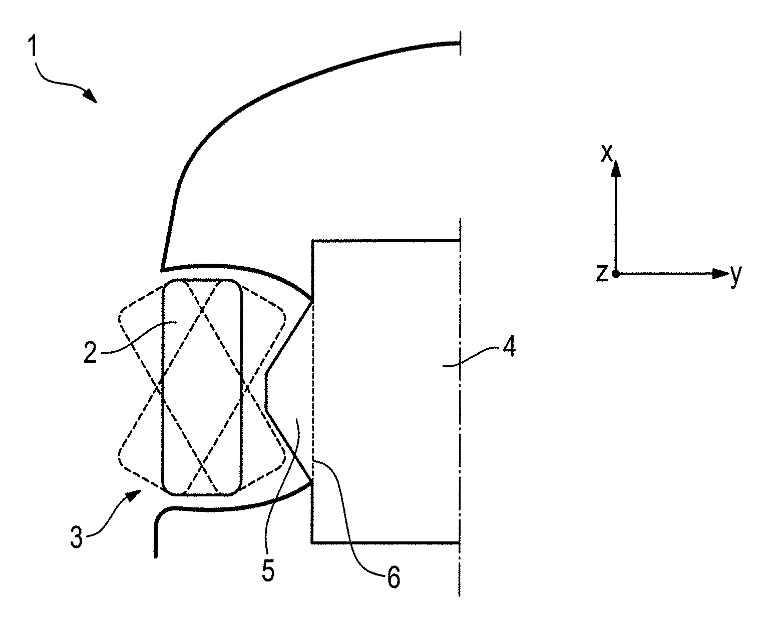
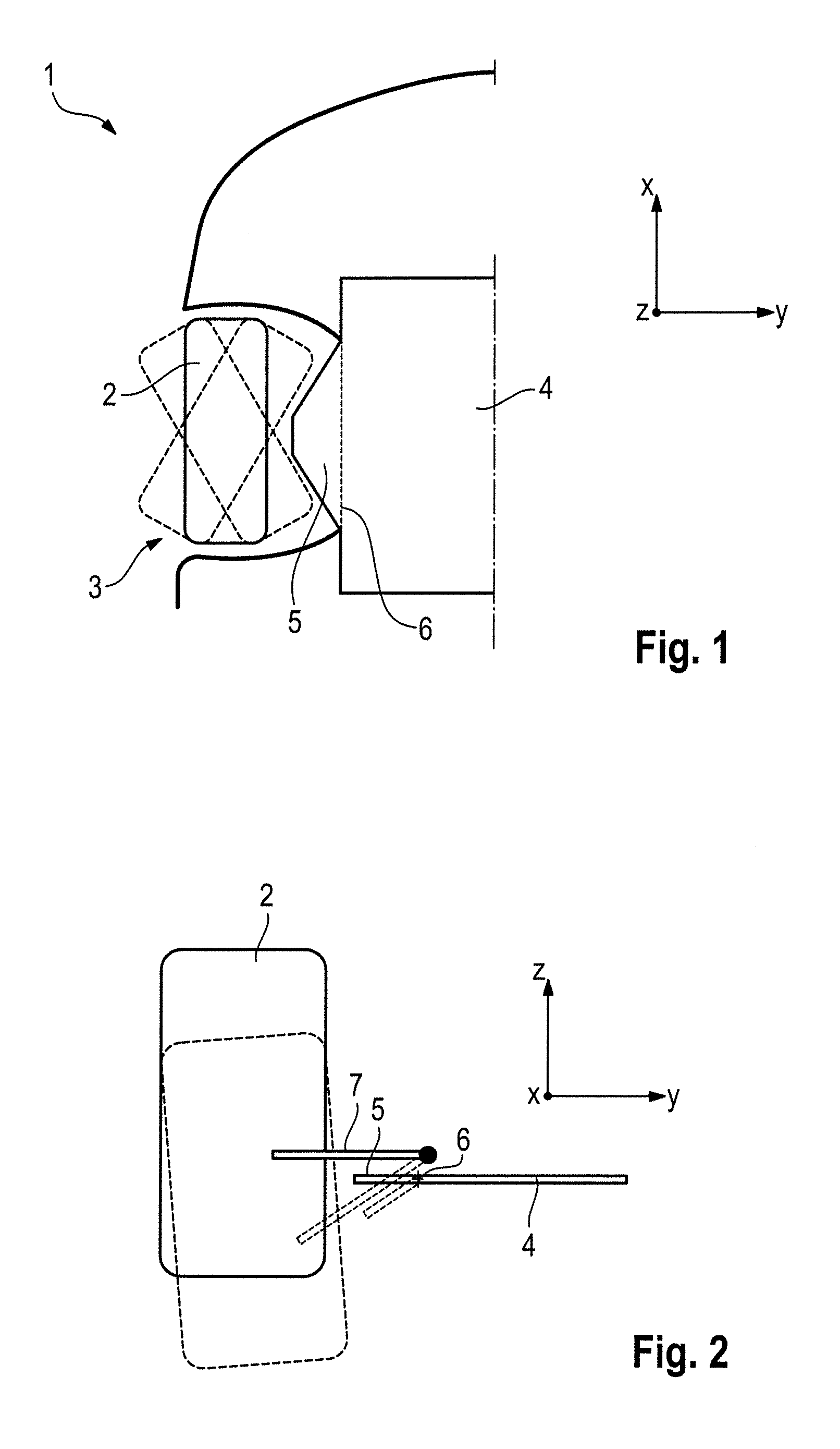
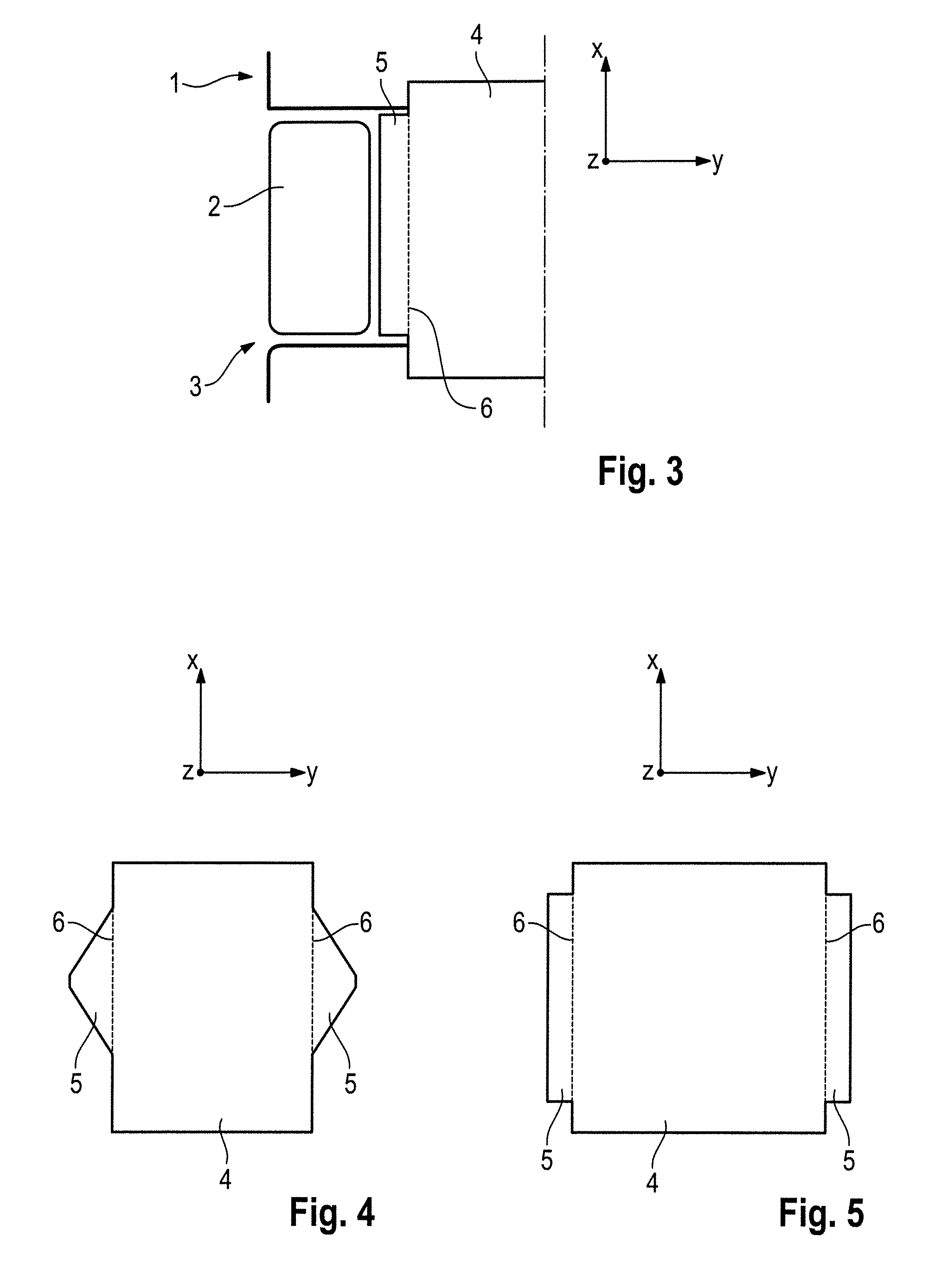
[0032]The space coordinates X, Y and Z are illustrated in each of the figures. The coordinate X constitutes the longitudinal direction of a vehicle, the coordinate Y constitutes the transverse direction of the vehicle and the coordinate Z constitutes the vertical direction of the vehicle. The coordinate X therefore points in forward direction of travel of the vehicle during straight-ahead travel and the coordinate Y points to the sides of the vehicle.

[0033]FIG. 1 is a bottom plan view of an area of a motor vehicle 1 in an area of the right front wheel 2 and schematically illustrates a first variant of the invention. The motor vehicle 1 may be a passenger vehicle, and the solid line depiction of the wheel 2 is for straight-ahead travel of the motor vehicle 1. The dashed illustrations of the wheel illustrate the maximum steering angle positions for travelling around a right or left bend.

[0034]The motor vehicle 1 has a wheel house 3 for receiving the wheel 2. An underbody panel 4 is pr...


PUM


Abstract

A motor vehicle (1) has a device (5) that projects into the wheel house (3) to reduce the flow of air into the wheel house (3) while the motor vehicle (1) is moving. The device (5) may extend from an underbody panel (4) of the motor vehicle (1) and may be pivotable about a longitudinal axis (6) of the motor vehicle (1) on a side of the underbody panel (4) that faces the wheel house (3). Alternatively, the device (5) is connected to a chassis component (7) of a wheel (2) arranged within the wheel house (3).

Description

CROSS REFERENCE TO RELATED APPLICATION[0001]This application claims priority under 35 USC 119 to German Patent Appl. No. 10 2013 108 762.0 filed on Aug. 13, 2013, the entire disclosure of which is incorporated herein by reference.BACKGROUND OF THE INVENTION[0002]1. Field of the Invention[0003]The invention relates to a motor vehicle with a wheel house and a pivotable device that projects into the wheel house to reduce the flow of air into the wheel house while the motor vehicle is moving.[0004]2. Description of the Related Art[0005]Air flows into the wheel house of a vehicle while the vehicle is moving, and therefore the air flowing around the vehicle is disturbed in the region of this region of the motor vehicle. Different solutions have been disclosed for reducing the flow of air into the wheel house while a motor vehicle is moving.[0006]U.S. Pat. No. 7,845,709 discloses a plate-like device that is pivotable about a vertical axis for reducing the flow of air into the wheel house w...

Claims


Application Information

Patent Timeline
Patent Type & Authority Applications(United States)
IPC IPC(8): B62D35/02B62D25/16
CPCB62D25/16B62D35/02Y02T10/88
Inventor WOLF, THOMAS
Owner DR ING H C F PORSCHE AG
Why Eureka
Try Eureka