
Disc rotor motor

a disc rotor motor and disc rotor technology, applied in the direction of magnetic circuits characterised by magnetic materials, magnetic circuit rotating parts, magnetic circuit shapes/forms/construction, etc., can solve the problems of large disc rotor motors that are unsuitable, low efficiency, and low torque densities, so as to improve the efficiency and power and torque density of disc rotor motors, and achieve high power and torque density. , the effect of no negative influence on the efficiency and power and torque density

Active Publication Date: 2015-02-19
MIBA SINTER AUSTRIA
View PDF10 Cites 19 Cited by
  • Summary
  • Abstract
  • Description
  • Claims
  • Application Information

AI Technical Summary

Benefits of technology

The invention relates to a disc rotor motor with ferrite magnets that can achieve a compact and weight-reducing design with high power and torque densities and high efficiency. The motor has stator teeth that widen out towards the end, allowing the permanent magnetic flux of the ferrite magnets to be introduced in a reliable and low-loss fashion into the stator. The tooth shape also reduces the size of the motor and enhances cooling. The invention presents a previously unknown potential application for disc rotor motors in automotive engineering.

Problems solved by technology

The disadvantages of using inexpensive ferrite magnets are that on the one hand, reduced power densities and on the other, lower torque densities are to be expected.
If the amount of available installation space is small, which is one of the challenges, for example, in automotive engineering, then such comparatively inexpensive, but large disc rotor motors are unsuitable.

Method used


Image

  • Disc rotor motor
  • Disc rotor motor
  • Disc rotor motor

Examples


Embodiment Construction

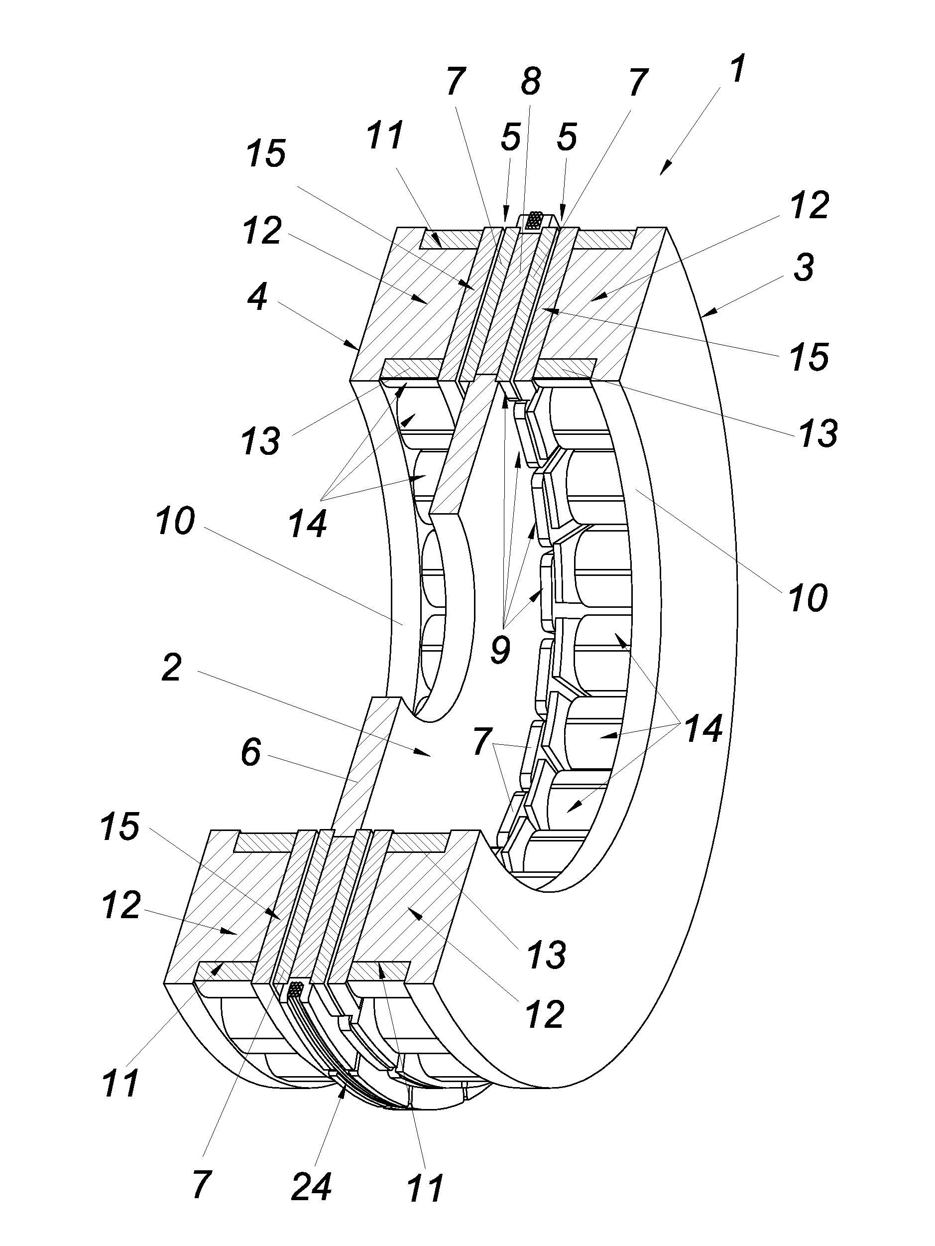
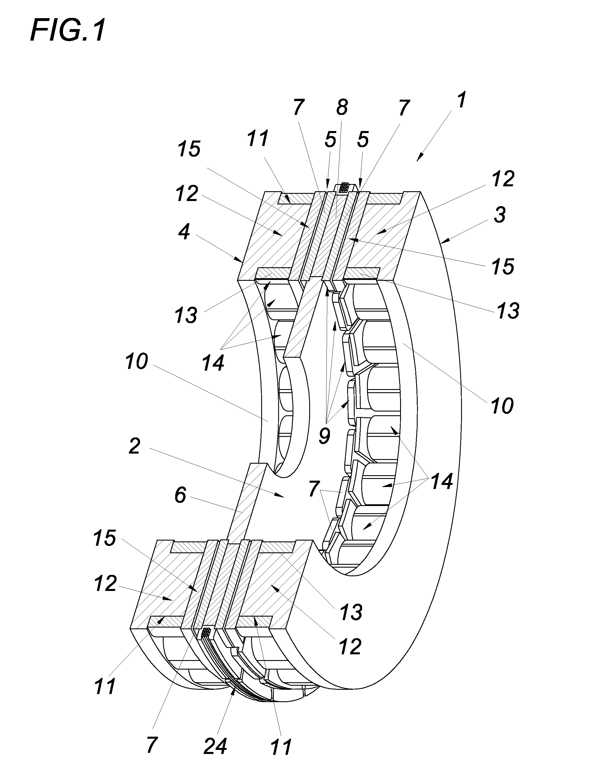
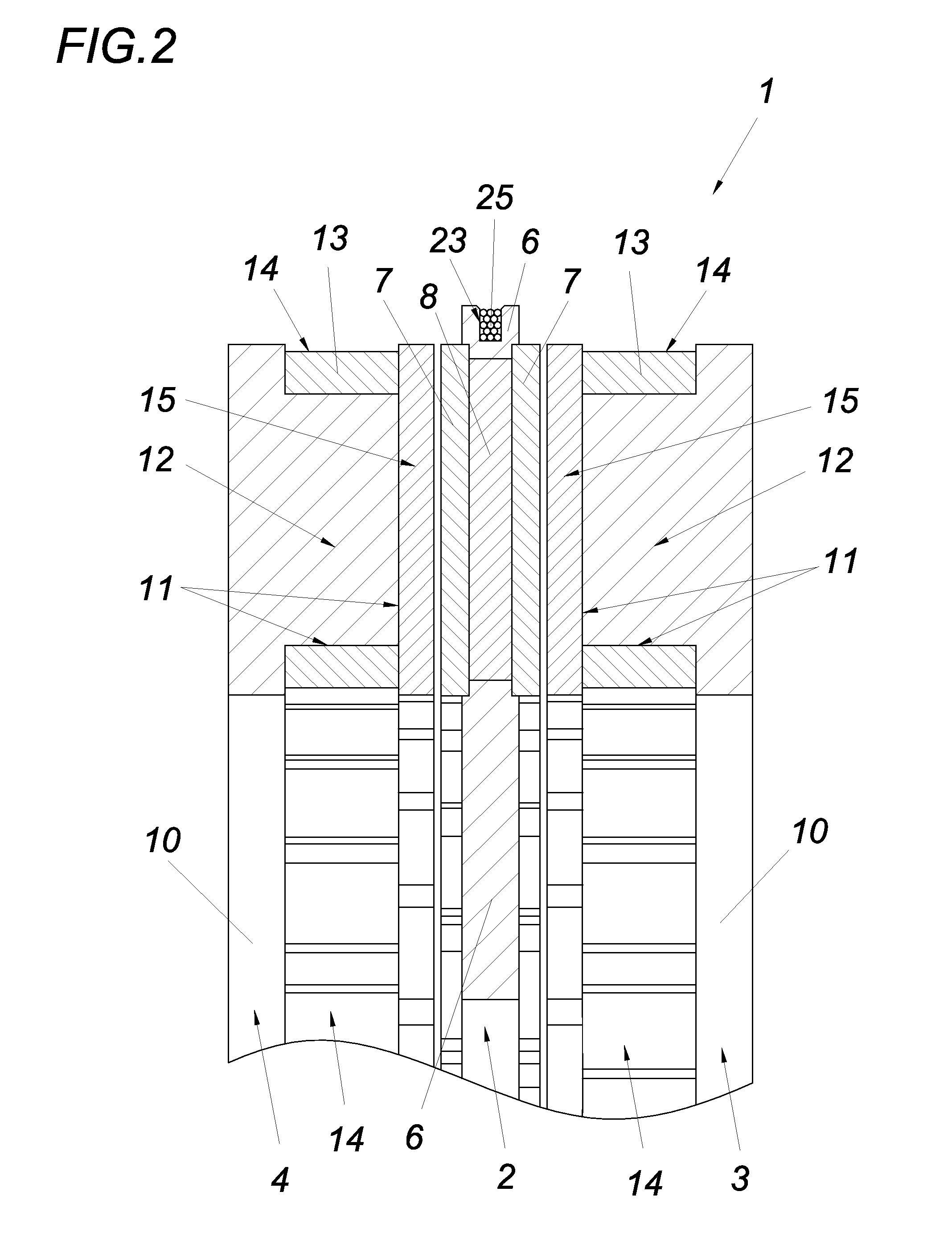
[0033]In the exemplary embodiment shown in FIG. 1, a two-sided disc rotor motor 1 is shown, which has a rotor 2 between two identically embodied stators 3, 4. The rotor 2 and the stators 3, 4 are oriented parallel to each other and are spaced apart from one another by a respective axial gap 5. As is clear from FIGS. 1, 2, and 4, the rotor 2 is disc-shaped, essentially influenced by its support disc 6. The support disc 6 is provided exclusively with ferrite magnets 7, 8 in order to produce permanent magnet-excited, torque-producing poles 9. It is also conceivable for these poles 9 to contribute to force generation, for example for the contactless support of the rotor 2, which is not shown in detail.

[0034]According to FIG. 1, each of the two identically embodied stators 3 and 4 is provided with a respective stator yoke 10, which ends in a plurality of parallel stator teeth 11. The stator teeth 11 or the tooth necks 12 are wound with coils 13 of a stator winding 14, which is preferably...


PUM


Abstract

A disc rotor motor is demonstrated, having at least one stator that has at least one electrical stator winding and stator teeth, which have a tooth neck composed of a soft magnetic powder composite, and having at least one disc-shaped rotor, which has permanent magnetic poles composed exclusively of ferrite magnets at least for producing torque, with the rotor and stator oriented parallel to each other and spaced apart from each other by an axial gap. In order to find an optimum between costs, weight, and overall size as well as power and torque density, the invention proposes that the stator teeth each end in a tooth end that adjoins their tooth neck and is composed of a soft magnetic powdered composite, which tooth end widens out in its cross-sectional area in comparison to the tooth neck.

Description

FIELD OF THE INVENTION[0001]The invention relates to a disc rotor motor, having at least one stator that has at least one electrical stator winding and stator teeth, which have a tooth neck composed of a soft magnetic powder composite, and having at least one disc-shaped rotor, which has permanent magnetic poles composed exclusively of ferrite magnets at least for producing torque, with the rotor and stator being oriented parallel to each other and spaced apart from each other by an axial gap.BACKGROUND OF THE INVENTION[0002]In order to produce a disc rotor motor with reduced material costs, the prior art (author: Sone, Kodai; et. al., title: “A Ferrite PM In-Wheel Motor Without Rare Earth Materials,” IEEE Transactions on Magnetics, 48(11): 2961-2964) has disclosed equipping a rotor embodied as a rotor disc exclusively with ferrite magnets in order to thus produce the permanent magnetic poles for torque production. It is therefore possible to avoid the need for permanent magnets mad...

Claims


Application Information

Patent Timeline
Patent Type & Authority Applications(United States)
IPC IPC(8): H02K1/14H02K1/27H02K9/22H02K1/02
CPCH02K1/14H02K9/22H02K1/2793H02K1/02H02K1/146H02K1/27H02K16/04H02K9/223H02K1/2796H02K21/24H02K1/148
Inventor KOBLER, RALFANDESSNER, DIETMARSANDNER, CHRISTIAN
Owner MIBA SINTER AUSTRIA
Learn More