Concentrator-Driven, Photovoltaic Power Generator
Active Publication Date: 2015-02-19
DAVOREN TRUSTEE JEFFREY
8 Cites 3 Cited by
AI-Extracted Technical Summary
Problems solved by technology
Although solar energy comprises a very abundant sourc...
Benefits of technology
[0009]The present invention is a novel and useful collection device for capturing and transmitting electromagnetic radiation received from the sun. The present invention incorporates a solar collector, lens(es), an infrared (IR) filter, and photovoltaic cell. Incoming solar radiation striking the face of the parabolic solar collector is reflected and concentrated at the focal point. As the radiation begins to diverge from the focal p...
Abstract
A concentrator-driven, photovoltaic power generator system and method for capturing and transmitting electromagnetic radiation utilizing a reflector having a concave reflecting surface for concentrating electromagnetic radiation to a focal point.
Application Domain
Photovoltaic supportsSolar heating energy +9
Technology Topic
PhysicsDynamo +5
Image
Examples
- Experimental program(1)
Example
[0023]For a better understanding of the invention reference is made to the following detailed description of the preferred embodiments thereof which should be taken in conjunction with the prior described drawings.
DETAILED DESCRIPTION OF THE PREFERRED EMBODIMENT
[0024]The description that follows is presented to enable one skilled in the art to make and use the present invention, and is provided in the context of a particular application and its requirements. Various modifications to the disclosed embodiments will be apparent to those skilled in the art, and the general principals discussed below may be applied to other embodiments and applications without departing from the scope and spirit of the invention. Therefore, the invention is not intended to be limited to the embodiments disclosed, but the invention is to be given the largest possible scope which is consistent with the principals and features described herein.
[0025]Various aspects of the present invention will evolve from the following detailed description of the preferred embodiments thereof which should be taken in conjunction with the hereinabove delineated drawings.
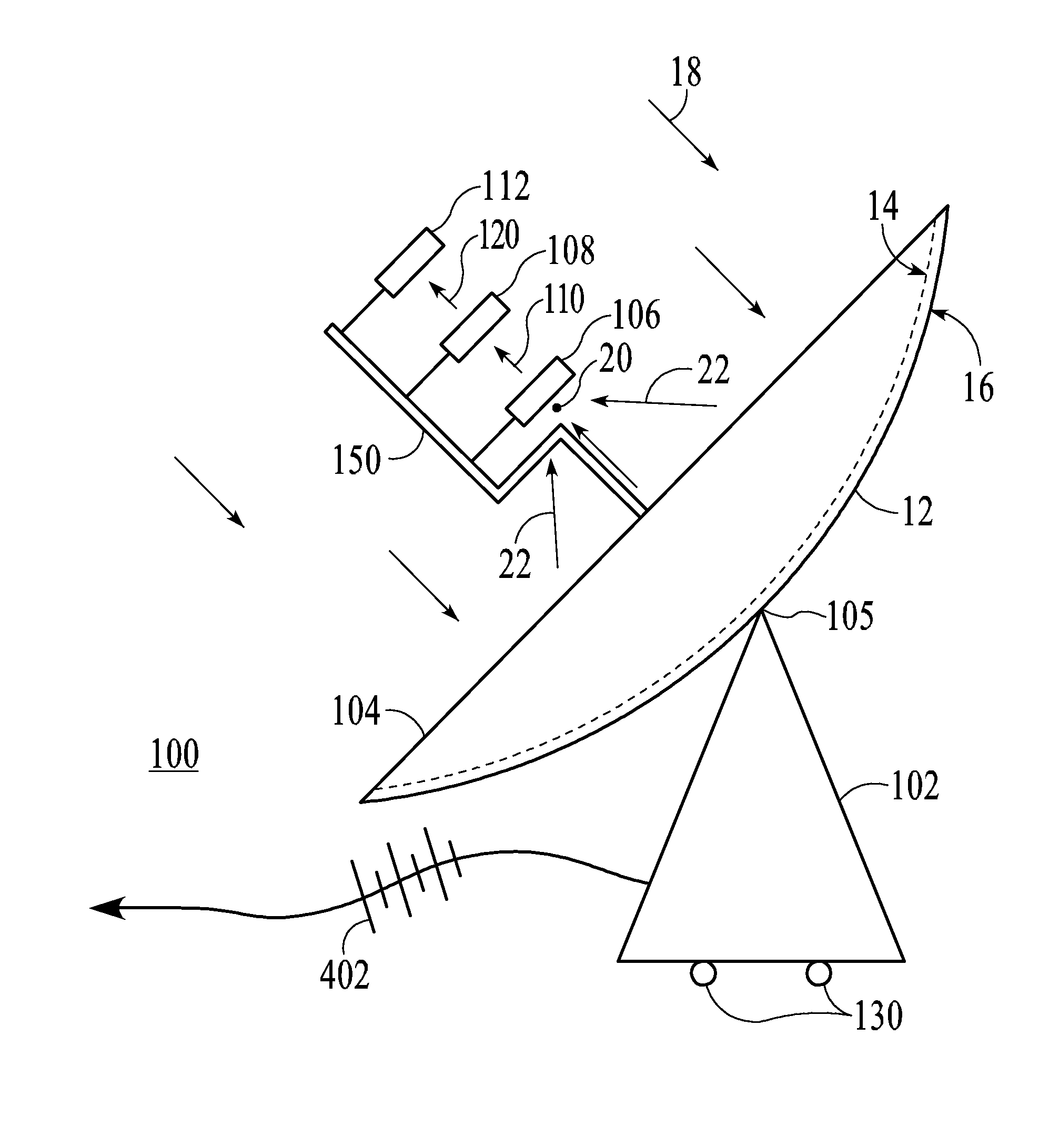
[0026]The present invention as a whole is shown in the drawings by reference character 100, and any upper case letter to represent various embodiments thereof. With respect to FIG. 1, concentrator-driven, photovoltaic power generator 100 consists of a parabolic-shaped reflector 12 and a mobile stand 102. Specifically, reflector 12 takes the form of a parabolic mirror having an inner reflecting surface 14 and an outer surface 16 which is generally non-reflective. In essence, reflecting surface 14 captures or gathers incoming parallel rays 18 from the sun. Reflecting surface 14 then reflects and focuses converging reflected rays 22 to the focal point 20. Reflected rays 22 indicate such concentration of electromagnetic radiation to focal point 20. As shown in FIGS. 1 and 2, a twice-bent hollow support tubing 150 or equivalent extends from the center of reflector 12 and provides anchor points for the electromagnetic radiation collection/storage system 200.
[0027]As shown in FIG. 1, reflector 12 is supported and elevated by mobile stand 102. In one embodiment, mobile stand 102 may be of a conventional configuration to provide a sturdy and stable base for reflector 12 in the outdoor environment. Reflector 12 is anchored, fixed, and pivots mechanically, flexibly and adjustably on mobile stand 102. Mechanical coupling device 105 such as a hinge, ball-and-socket joint, universal joint, etc., permits reflector 12 to rotate and move about its center point. This allows a controllable range of two-dimensional motion such that it is capable of tracking the sun as it travels across the sky on a daily orbital basis. Mechanical device 105 can be manually operated or controlled with an electrical/electronic motor. Support stand 102 can be mobile with wheels or other means such as wheels-and-track system 130 so the entire power generator 100 can be moved or relocated to locations that are most receptive to strong sun exposure. Since such two-axis tracking system supports are known in the art, mobile stand 102 is only partially shown in the drawings. In one embodiment, physical locations of the present invention 100 in the wheels-and-track system 130 and titling angles of reflector 12 can both be pre-programmed according to locations of the sun during the day/year.
[0028]FIG. 2 is a representative sectional view of the concentrator-driven, photovoltaic power generator 100 of the present invention. FIG. 3 is a schematic view of the mechanism of concentrator-driven, photovoltaic power generator 200 of the present invention. Referring to FIG. 3, the concentrator-driven, photovoltaic power generator 200 consists one or more intermediary lens assembly 106, infrared filter device 108 and photovoltaic cell 112. The three elements of the concentrator-driven, photovoltaic power generator 200 are installed and supported securely by each of its support stands 152, 154 and 156 on the twice-bent hollow support tubing 150 which extends from the center of reflector 12. In one embodiment, the three elements are disposed in a straight line sequence of intermediary lens assembly 106→infrared filter device 108→photovoltaic cell 112 with the intermediary lens assembly positioned closest to reflector 12. The intermediary lens assembly is positioned at the focal point 20 where all converging reflected rays 22 from reflector 12 are gathered. In one embodiment, support tubing 150 is a hollow tubing that has a squarish cross-section and is made of steel, plastic, silicon or other sturdy and yet strong materials. It will be understood by those skilled in the art that support tubing can be substituted with equivalent structural components for achieving the same function.
[0029]In one embodiment, intermediary lens assembly 106 which is a type of optical lens fixed at the focal point 20, where the converging reflected rays or concentration of electromagnetic radiation 22 enter intermediary lens assembly 106. Intermediary lens assembly 106 can be in the form of a lens or a lens assembly that alters the converging reflected rays or concentration of electromagnetic radiation 22 into a concentrated, uni-directional flow of solar energy 110. The optical characteristics such as focal length, shape, i.e., concave, convex or combination thereof, etc., of intermediary lens assembly 106 can be adjusted according to the true dimension of the power generator 100. In one embodiment, parallel rays 18 from the sun are reflected by reflector 12 to become converging rays 22 at focal point 20. The main purpose of reflector 12 is to concentrate the energy of parallel rays 18 at focal point 20 for effective energy collection. Subsequently, at and around focal point 20, converging reflected rays 22 pass through intermediary lens assembly 106 and emerge as a concentrated, uni-directional flow of visible-wavelength solar energy 110. The present invention minimizes energy loss due to internal reflection or other reasons.
[0030]In one embodiment, intermediary lens assembly 106 is movably fixed to support tubing 150 by its support stand 152 such that the position of the intermediary lens assembly 106 can be adjusted in order to be located at or as close to the focal point 20 as possible for maximum efficiency. Since it is possible that a portion of the uni-directional flow of solar energy 110 will contained energy in the infrared wavelength-range, the system could develop overheating problems. Thus, the uni-directional flow of solar energy 110, i.e., parallel radiation, leaves intermediary lens assembly 106 and enters infrared filter device 108.
[0031]Infrared filter device 108 is an infrared cut-off filter, sometimes called an IR filter or heat-absorbing filter. In one embodiment, infrared filter device 108 is movably fixed to support tubing 150 by its support stand 154. The purpose of infrared filter device 108 is to block infrared wavelength-radiation in the uni-directional flow of solar energy 110 while passing uni-directional flow of filtered solar energy 120 to prevent overheating when it enters photovoltaic cell 112. In alternative embodiments, other types of filters such as UV filter or other wavelength-specific filters can be added or replaced as needed.
[0032]Filtered uni-directional flow of solar energy 120, i.e., parallel radiation, leaves infrared filter device 108 and enters photovoltaic cell 112. Photovoltaic cell 112 is a device that converts the photonic energy of incoming filtered visible wavelength, uni-directional flow of solar energy 120 directly into electricity by the photovoltaic effect. In one embodiment, photovoltaic cell 112 has various electrical characteristics e.g. current, voltage, or resistance to suit specific needs of the present invention 100. Generally, when photovoltaic cell 112 exposed to uni-directional flow of solar energy 120, it generates and supports an electric current without the need for any external power source.
[0033]In one embodiment, photovoltaic cell 112 is movably fixed to support tubing 150 by its support stand 156. Photovoltaic cell 112 is also connected to an electric circuit so the electrical energy generated within can be transmitted to remote locations. In one embodiment, the electric circuit can be installed within the hollow support tubing 150 or other configurations. As best shown in FIG. 4, in one embodiment, photovoltaic cell 112 converts energy from filtered uni-directional flow of solar energy 120 into electrical energy denoted by electrical potential 402. Electrical potential 402 can be coupled to a capacitor or used to recharge batteries for storage of the electrical energy generated, as desired. Alternatively, the energy potential 402 can be used to power electrical devices directly. Users can also connect energy potential 402 to a more elaborate electrical circuit with other electrical components such as transducers, transformers, etc. for other purposes, or provide electrical power to the grid, i.e., puts power back into a private or general municipal electrical power system.
[0034]While in the foregoing, embodiments of the present invention have been set forth in considerable detail for the purposes of making a complete disclosure of the invention, it may be apparent to those of skill in the art that numerous changes may be made in such detail without departing from the spirit and principles of the invention.
[0035]Although the invention herein is to be understood as described, these descriptions are merely illustrative of the principles and applications of the present invention. Therefore, it is understood that numerous modifications may be made to the illustrative embodiments and that other modifications maybe devised without departing from the scope and functions of the inventions as defined by the claims to be followed.
[0036]Unless defined otherwise, all technical and scientific terms used herein have the same meaning as commonly understood by one of ordinary skill in the art to which the present invention belongs. Although any methods and materials similar or equivalent to those described can be used in the practice or testing of the present invention, the preferred methods and materials are now described. All publications and patent documents referenced in the present invention are incorporated herein by reference.
[0037]While the principles of the invention have been made clear in illustrative embodiments, there will be immediately obvious to those skilled in the art many modifications of structure, arrangement, proportions, the elements, materials, and components used in the practice of the invention, and otherwise, which are particularly adapted to specific environments and operative requirements without departing from those principles. The appended claims are intended to cover and embrace any and all such modifications, with the limits only of the true purview, spirit and scope of the invention.
PUM


Description & Claims & Application Information
We can also present the details of the Description, Claims and Application information to help users get a comprehensive understanding of the technical details of the patent, such as background art, summary of invention, brief description of drawings, description of embodiments, and other original content. On the other hand, users can also determine the specific scope of protection of the technology through the list of claims; as well as understand the changes in the life cycle of the technology with the presentation of the patent timeline. Login to view more.