Micro-Optical Cavity with Fluidic Transport Chip for Bioparticle Analysis

a micro-optical cavity and bioparticle technology, applied in the field of biological specimen analysis, can solve the problems of false readings and pathologists relying on labor-intensive microscopic examination, and achieve the effects of rapid, accurate analysis of optical properties, and calibration and maintaining measurement fidelity during operation

Active Publication Date: 2015-02-19
GOURLEY PAUL L
View PDF29 Cites 22 Cited by
  • Summary
  • Abstract
  • Description
  • Claims
  • Application Information

AI Technical Summary

Benefits of technology

[0011]It is also an object of this method to extract the refractive index distribution from the measured laser wavelength shift Δλ distribution. It is also a surprising advantage that a bioparticle (as small as hundreds of nanometers in size) can be individually and rapidly (in microseconds) measured for its refractive index. It is also a surprising advantage that the optical properties can be directly related to the biomolecular composition of the particle, and that the distribution of the optical property among a population of like particles can be well-described by simple, analytic probability functions. When the biomolecular composition is altered as in a stressed or diseased cell, the optical properties and their distribution change in a manner that can be measured and analyzed with the statistical model.
[0013]It is a further object of this invention to simplify the apparatus for measuring bioparticles by using a resonant optical cavity without a gain medium. This has the advantage of making the apparatus less costly to fabricate and facilitates both size and optical density measurement.

Problems solved by technology

To investigate tumors, pathologists currently rely on labor-intensive microscopic examination, using older cell-staining methods that can be time-consuming and may give false readings.

Method used


Image

  • Micro-Optical Cavity with Fluidic Transport Chip for Bioparticle Analysis
  • Micro-Optical Cavity with Fluidic Transport Chip for Bioparticle Analysis
  • Micro-Optical Cavity with Fluidic Transport Chip for Bioparticle Analysis

Examples


microscopy embodiment

[0099

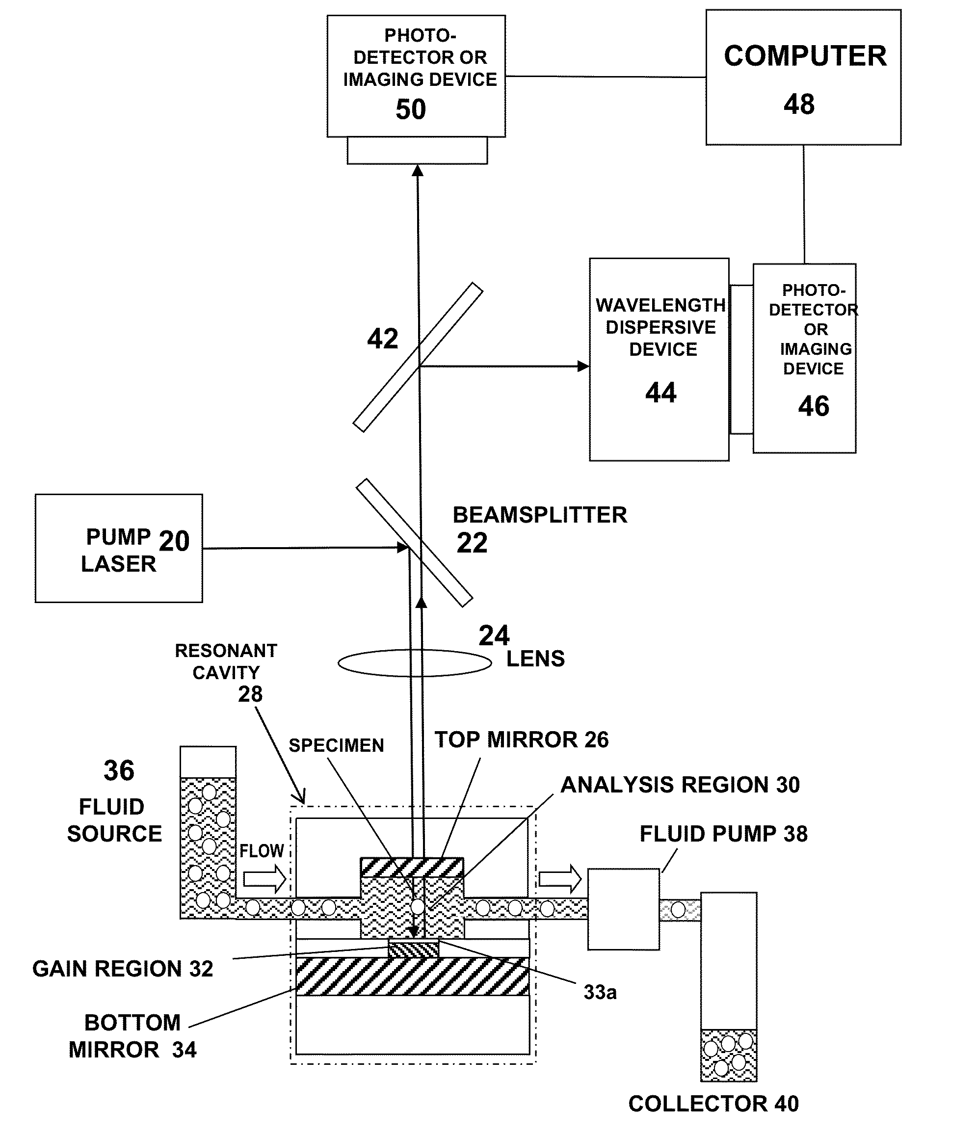
[0100]Another embodiment of the measurement and analysis method is to use multiple beam interference microscopy with an apparatus shown in FIG. 7 through 9. In FIG. 7 light from source 52 is directed toward a resonant cavity (with or without gain) 28 with lens 54 and then the image of the cavity is relayed with lens 24 to a imaging device 50 and / or to a spectroscopy / detector device 44 / 46. The output of these devices is linked to a computer 48 for analysis. The light source could be a laser, LED, lamp, fiber optic source or the like. Alternately the light source could be contained in the cavity (semiconductor, fluorescent material, or the like). The light interacts with the cavity to establish optical resonances that can be observed by a detector. These conditions can be detected by the imaging device or spectral device. When bioparticles are inserted into the cavity, the light interacts with the particle / cavity and produces a light signal (transmitted, reflected, scattered, flu...


PUM

PropertyMeasurementUnit
sizeaaaaaaaaaa
wavelengthsaaaaaaaaaa

Abstract

This invention provides new methods and apparatus for rapidly analyzing single bioparticles to assess their material condition and health status. The methods are enabled by a resonant cavity to measure optical properties related to the bioparticle size and refractive index. Refractive index measurements are useful for determining material properties and biomolecular composition of the bioparticle. These properties and composition are dependent on the health state of the bioparticle. Thus, measured optical properties can be used to differentiate normal (healthy) and abnormal (diseased) states of bioparticles derived from cells or tissues. The methods are illustrated with data obtained from a resonator with a gain medium. The invention also provides new methods for multiple measurements in a single device, analyzing and manipulating bioparticles that are much smaller than the wavelength of light, and provides a microfluidic transport chip to enable rapid single bioparticle analysis of large populations of bioparticles.

Description

CROSS REFERENCE TO RELATED APPLICATIONS[0001]This application is a Continuation in Part application Ser. No. 12 / 34,640 filed on Feb. 21, 2008. This application claims priority benefit from U.S. Provisional Patent Application Ser. No. 60 / 902,685, filed on Feb. 21, 2007, which is incorporated herein by reference.STATEMENT REGARDING FEDERALLY SPONSORED R&D[0002]This invention was made with partial Government support under Contract No. DE-AC04-94AL85000 awarded by the U.S. Department of Energy to Sandia Corporation for the management and operation of the Sandia National Laboratories. Sandia has waived its rights to the Department of Energy which has in turn waived rights to the inventor. The Government retains certain rights in the invention.BACKGROUND OF THE INVENTION[0003]1. Field of the Invention[0004]This invention relates to methods of analyzing biological specimens using biological micro-electromechanical systems (bioMEMs). The invention includes analysis methods and apparatus use...

Claims


Application Information

Patent Timeline
Patent Type & Authority Applications(United States)
IPC IPC(8): G01N33/483G01N15/14
CPCG01N33/4833G01N2015/1493G01N15/1404G01N15/1484G01N15/1436G01N21/47G01N21/6428G01N21/7746G01N33/574G01N2015/1006G01N2015/1409G01N2015/1495
Inventor GOURLEY, PAUL L.
Owner GOURLEY PAUL L
Why Eureka
Try Eureka