Injection molding apparatus

a technology of injection molding and molding apparatus, which is applied in the field of injection molding apparatus, can solve the problems of complex control of molding conditions and large size of the entire apparatus, and achieve the effect of simple control molding and desired accuracy

Active Publication Date: 2015-02-19
SATOSEIKI
View PDF7 Cites 1 Cited by
  • Summary
  • Abstract
  • Description
  • Claims
  • Application Information

AI Technical Summary

Benefits of technology

[0017]The injection molding apparatus according to the present invention enables apparatus size reduction and simple control manufacturing of moldings with a desired accuracy.

Problems solved by technology

In the above injection molding apparatus, the heating cylinder and the mold are separated, and the structure and molding conditions are independently devised from an aspect of control so that the optimum performance is fulfilled in both components, therefore, the entire apparatus has become large in size as well as the control of molding conditions has become complicated.

Method used


Image

  • Injection molding apparatus
  • Injection molding apparatus
  • Injection molding apparatus

Examples


Embodiment Construction

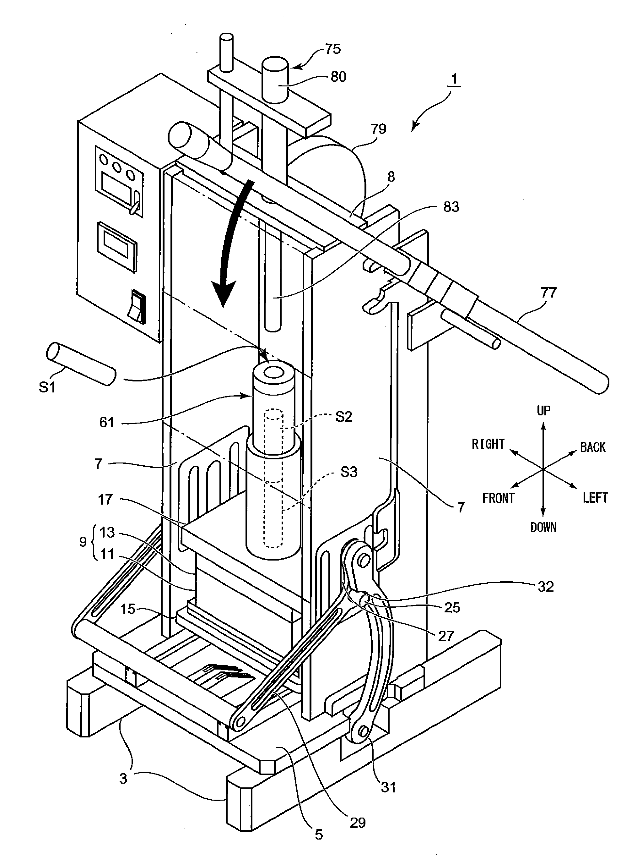
[0034]An injection molding apparatus 1 according to an embodiment of the present invention will be explained with reference to the drawings.

[0035]In FIG. 1, numerals 3, 3 denote a pair of leg portions and a mounting base 5 is fixed on the pair of leg portions 3, 3. A pair of side plates 7, 7 is installed to stand on right and left both end sides of the mounting base 5 so as to be parallel to each other. In the side plates 7, 7, plate surfaces face right and left directions, and front and back directions in which the side plate 7 does not exist are opened. A top plate 8 is disposed between upper end surfaces of the side plates 7, 7.

[0036]In a space surrounded by the mounting base 5, the right and left side plates 7, 7 and the top plate 8, a mold 9 and an injection cylinder 61 are arranged, in which the injection cylinder 61 is positioned above the mold 9.

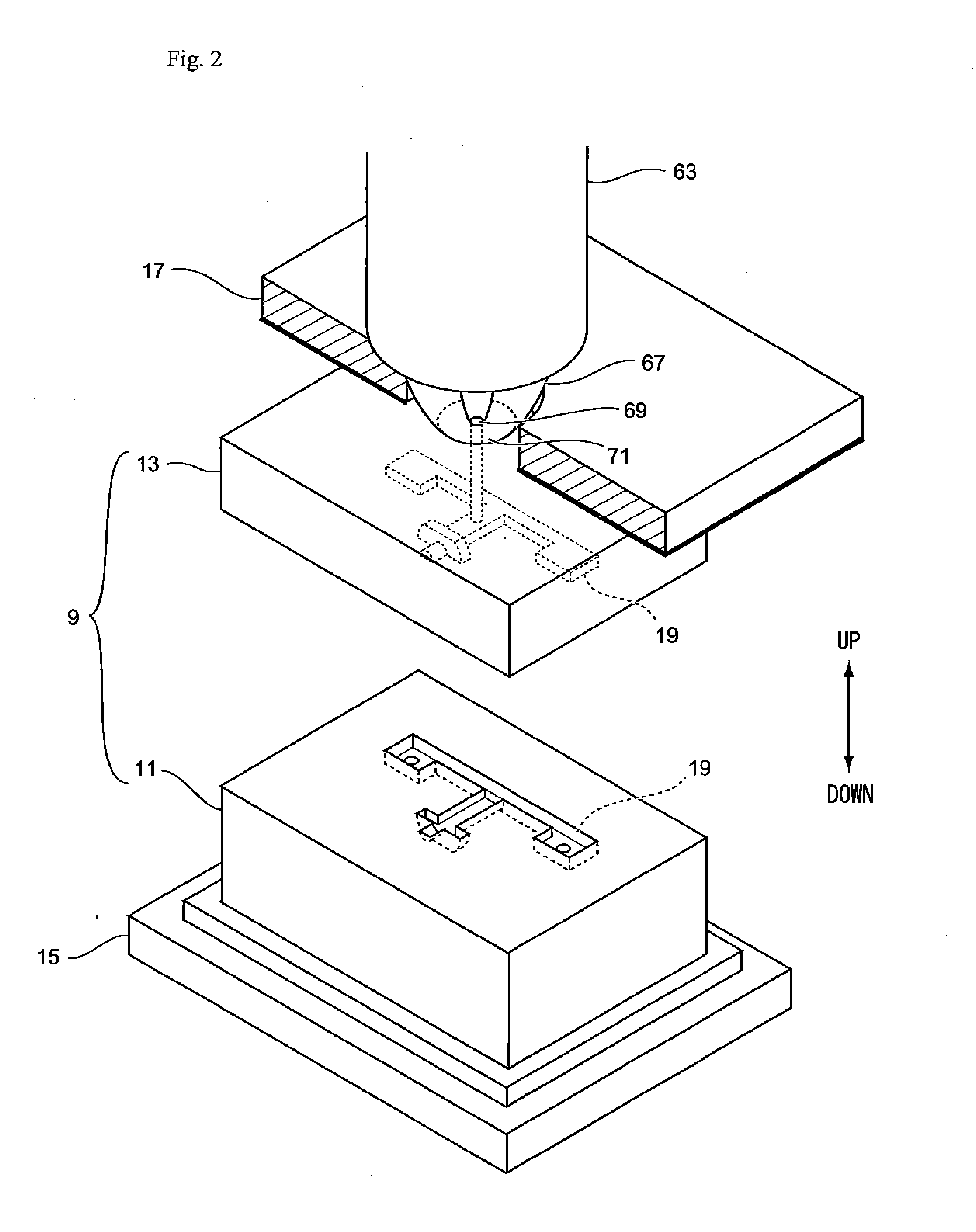
[0037]A section of the mold 9 will be explained at the beginning.

[0038]First, the structure of the mold 9 will be explained.

[0039]A...


PUM

PropertyMeasurementUnit
temperatureaaaaaaaaaa
heat retaining propertyaaaaaaaaaa
heat radiation propertyaaaaaaaaaa

Abstract

A small sized injection molding machine by which a molded product can be produced with a desired level of precision with simple control. An injection molding machine with: a longitudinal injection cylinder to which stick-shaped molding materials are sequentially supplied in line from the upper side, the lower end of which is formed into a nozzle shape, and the lower side of which is constituted by a material having a good heat retaining property; a heater which heats the lower portion of the injection cylinder; and a pressing shaft which presses the stick-shaped molding materials downward. When the stick shaped-molding material located at the uppermost side is pressed by the pressing shaft, the molding material located at the lowermost side which has already been completely melted, is injected into a cavity, and the heat from the heater is transmitted to the die side through a nozzle touch portion.

Description

TECHNICAL FIELD[0001]The present invention relates to a downsized and simplified injection molding apparatus.BACKGROUND ART[0002]In a related-art injection molding apparatus, a synthetic resin molding material, which has been supplied from a hopper in a form of pellets and the like, is plasticized and molten in a heating cylinder, then, is carried by a screw and injected to a mold cavity to be molded. Then, after the molding is solidified, the mold is opened and the molding is pushed out by an ejector pin.[0003]In the above injection molding apparatus, the heating cylinder and the mold are separated, and the structure and molding conditions are independently devised from an aspect of control so that the optimum performance is fulfilled in both components, therefore, the entire apparatus has become large in size as well as the control of molding conditions has become complicated.CITATION LISTPatent Literature[0004]Japanese Laid Open Patent Literature 1: JP-A-2008-302634SUMMARY OF INV...

Claims


Application Information

Patent Timeline
Patent Type & Authority Applications(United States)
IPC IPC(8): B29C45/18B29C45/74
CPCB29C45/74B29C45/1808B29C45/03B29C45/462B29C45/531
Inventor SATO, TOSHIOMI
Owner SATOSEIKI
Why Eureka
Try Eureka