Impeller for axial flow pump

a technology of axial flow and pump, which is applied in the direction of liquid fuel engines, prostheses, etc., can solve the problems of limited design improvement of the rotor, a formidable engineering challenge, and a theoretical infinite life of the pump, and achieve the effect of improving the blood pump

Active Publication Date: 2015-02-19
HEARTWARE INC
View PDF4 Cites 87 Cited by
  • Summary
  • Abstract
  • Description
  • Claims
  • Application Information

AI Technical Summary

Benefits of technology

[0013](c) an average outflow angle less than 30 degrees. Alternatively or additionally, the pressure surface of each said blade may include an outflow corner surface at the outflow end of the blade, the outflow corner surface extending over a major portion of the spanwise extent of the blade. Desirably, the outflow corner surface slopes in the rearward circumferential direction in the downstream axial direction Most preferably, the outflow corner surface extends to within 0.4 mm, and more pre of the suction surface of the blade at a downstream extremity of the blade.
[0014]A further aspect of the present invention provides an improved blood pump. The pump preferably includes a rotor as discussed above. The pump desirably has a hous

Problems solved by technology

Such a pump has theoretically infinite life.
Such improvement poses a formidable engineering chal

Method used


Image

  • Impeller for axial flow pump
  • Impeller for axial flow pump
  • Impeller for axial flow pump

Examples


Embodiment Construction

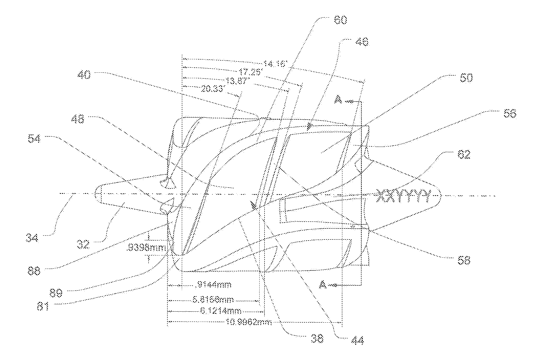
[0031]As used in this disclosure, the term “generally helical” refers to a feature which extends in the direction parallel to an axis and which curves in the circumferential direction around the axis over at least 50% of its extent in the direction along the axis. The degree of curvature and pitch of a helical feature need not be uniform.

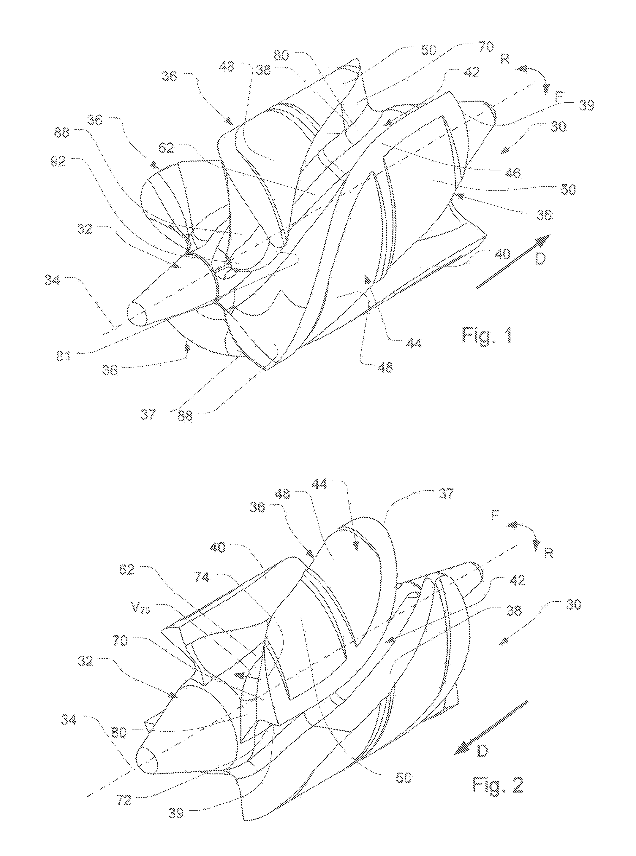
[0032]A rotor 30 according to one embodiment of the invention includes a unitary body incorporating a hub 32 extending along an axis 34. Directions along axis 34 are referred to herein as the “upstream” and “downstream” directions. Both such directions are also referred to herein as “axial” directions. The downstream direction is indicated in each of FIGS. 1 and 2 by the arrow D; the upstream direction is the opposite direction.

[0033]A plurality of blades 36, in this instance 4 blades, project from the hub. Each blade 36 extends out of the hub in an outward radial or “spanwise” direction perpendicular to axis 30. Each blade also extends in the lengt...


PUM


Abstract

A rotor for an axial-flow blood pump has blades projecting outwardly from a hub and channels between the blades. The blades incorporate hydrodynamic bearing surfaces capable of suspending the rotor during operation. The rotor has a configuration which provides superior pumping action and reduced shear of blood passing through the pump. The forwardly facing pressure surfaces of the blades may include outflow corner surface at their downstream ends. The outflow corner surfaces desirably slope rearwardly and intersect the rearwardly-facing suction surfaces of the blades at outflow ends of the blades.

Description

CROSS-REFERENCE TO RELATED APPLICATIONS[0001]The present application claims the benefit of the filing dates of U.S. Provisional Patent Application Nos. 61 / 865,672, filed Aug. 14, 2013, and 62 / 013,271, filed Jun. 17, 2014, the disclosures of which are hereby incorporated herein by reference.BACKGROUND OF THE INVENTION[0002]The present invention relates to rotors for use in blood pumps and to blood pumps having such rotors.[0003]Implantable blood pumps are employed as ventricular assist devices to aid the functioning of a diseased heart in a human patient or non-human animal subject. When a blood pump is employed as a left ventricular assist device or “LVAD,” an inlet of the pump communicates with the left ventricle of the patient's heart, whereas the outlet of the pump communicates with the aorta downstream of the aortic valve. Thus, the pump acts in parallel with the patient's left ventricle to impel blood from the ventricle into the aorta. A pump used as an LVAD in a typical human ...

Claims


Application Information

Patent Timeline
IPC IPC(8): A61M1/10A61M1/12
CPCA61M1/1036A61M1/122A61M1/1017F04D29/0413F04D29/181A61M60/824A61M60/422A61M60/148A61M60/237A61M60/178A61M60/806A61M60/419
Inventor TASKIN, MUSTAFA ERTAN
Owner HEARTWARE INC
Why Eureka
Try Eureka