Device and method for transferring workpieces into and out of a tool

a technology of workpieces and tools, applied in metal-working feeding devices, manufacturing tools, transportation and packaging, etc., can solve the problems of reducing reducing the cost of parts. , to achieve the effect of improving the degree of precision of parts, improving the degree of tool compactness, and increasing the number of strokes and economic efficiency

Active Publication Date: 2015-02-26
FEINTOOL INT HLDG
View PDF1 Cites 4 Cited by
  • Summary
  • Abstract
  • Description
  • Claims
  • Application Information

AI Technical Summary

Benefits of technology

[0004]An object of the invention is to provide a device and a method for transferring work pieces in and out of multi-staged cutting and processing tools that eliminates the need to move the slide into and out of the tool while at the same time increasing the number of strokes and economic efficiency, degree of precision in the parts, improved compactness in the tool, and a simplified design.

Problems solved by technology

This results in the cutting plate having both a cutting function and a transport function, which leads on one hand to a complicated design of the fine blanking tool and on the other hand encourages wear in the cutting plate due to the continuous sequence of aligning and locating in order to cut the work pieces and the rotational movement to transport the work pieces.
For multi-staged tools, this means that each work operation can only be carried out after the cross slide is moved out of the tool.
The time it takes to open the tool must be accounted for, increasing the finishing time per part and decreasing productivity.
Also, the linear slides require sufficient space and therefore make compact tool design difficult.

Method used


Image

  • Device and method for transferring workpieces into and out of a tool
  • Device and method for transferring workpieces into and out of a tool
  • Device and method for transferring workpieces into and out of a tool

Examples


Embodiment Construction

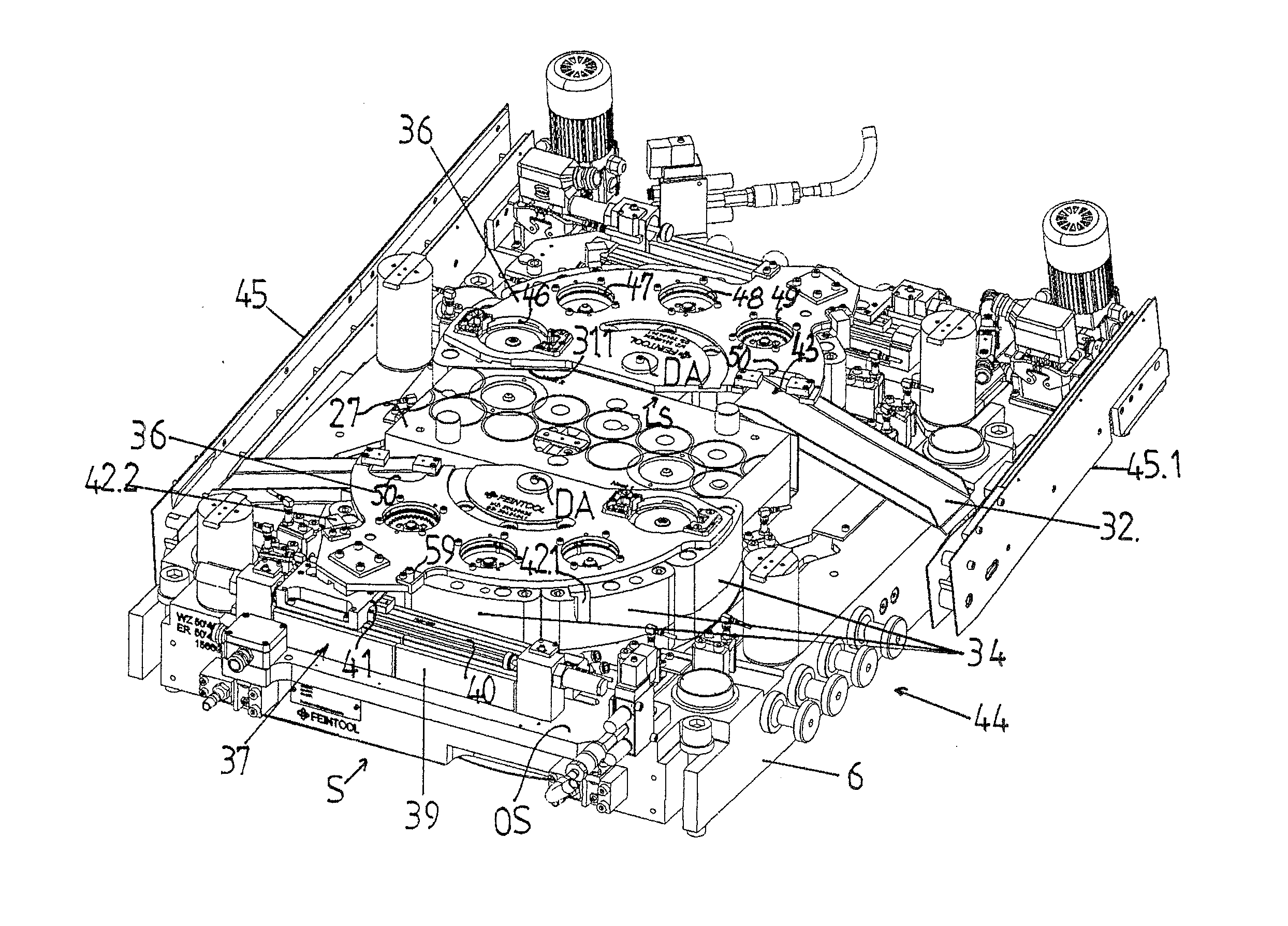
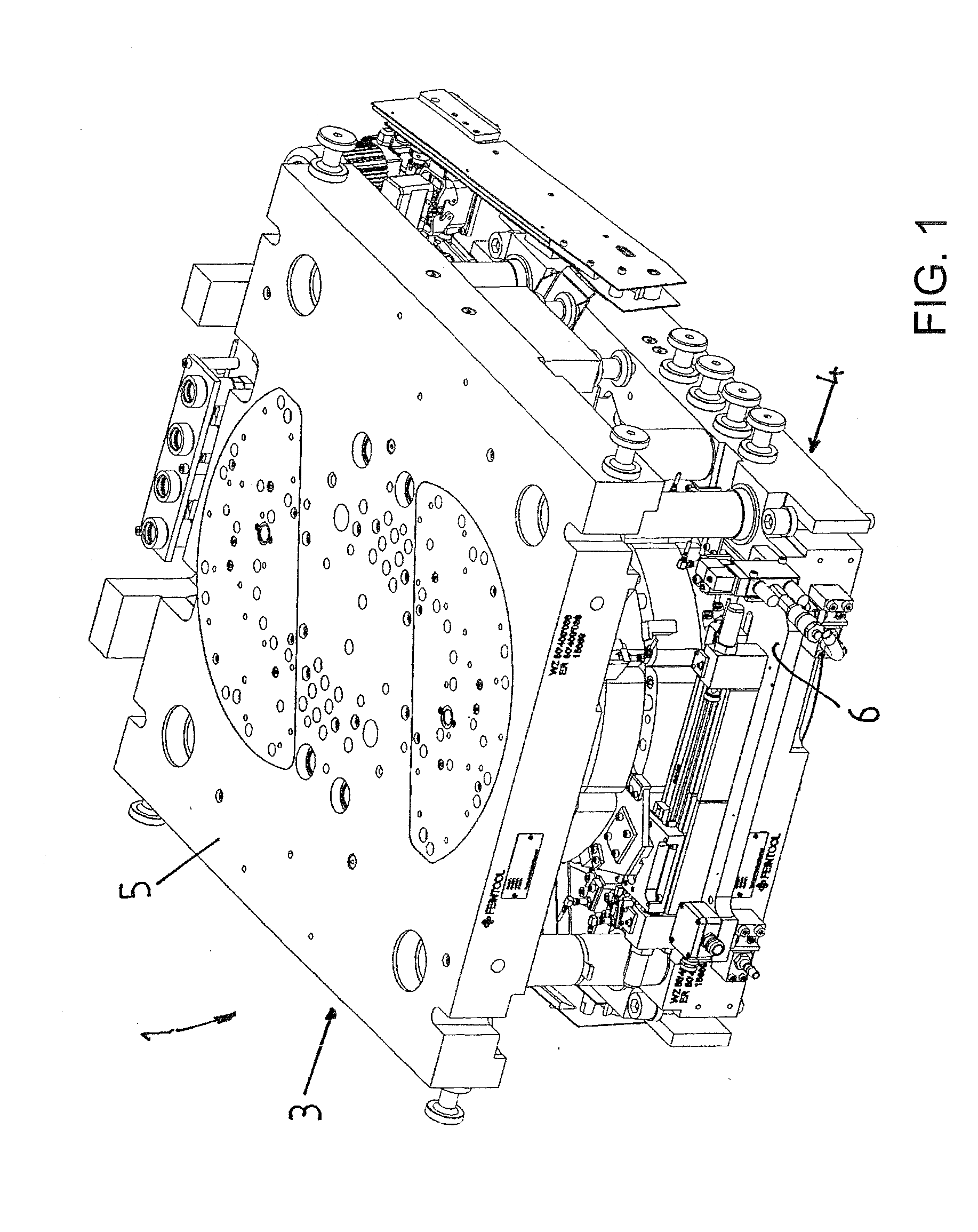
[0039]FIG. 1 shows a cutting and processing tool 1 for cutting a blank 2 and processing it into a finished work piece 57 (see FIG. 11). The cutting and processing tool 1 is made up essentially of an upper part 3 and a lower part 4. The upper part 3 is immovably fixed, by way of the upper Hock 5 thereof, to a machine table, which is not further shown, and is fixed by way of the lower block 6 thereof by a ram of a press, such that the blank 2 is cut out upward from a flat strip 7 from below, which is to say, toward the upper part, in the cutting stage 8 and 8.1.

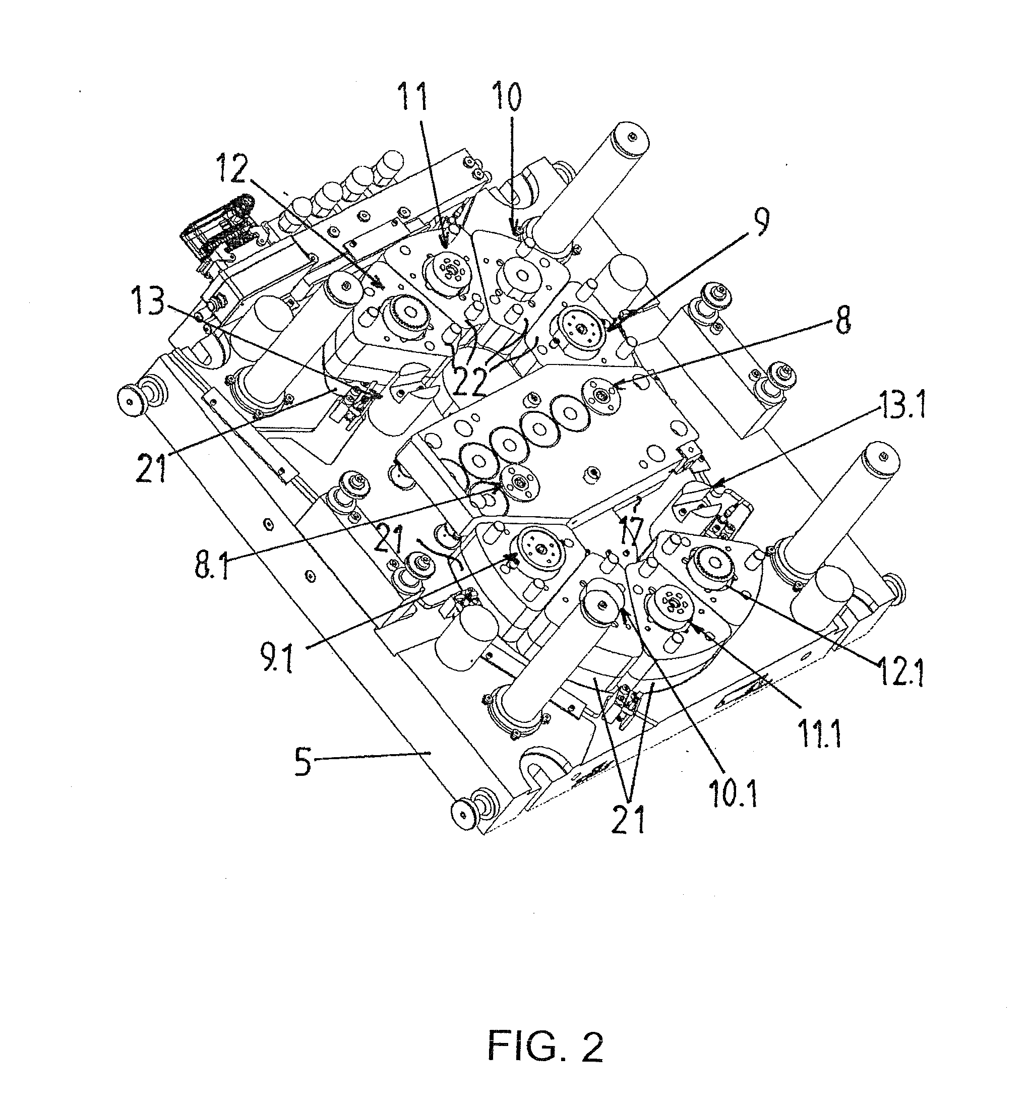
[0040]The cutting and processing tool 1 has two cutting stages 8 and 8.1 separated from one another in the direction of travel R of the strip and a plurality of processing stages 9 to 12 and 9.1 to 12.1 per cutting stage, respectively, as well as one discharge stage each 13 and 13.1. As shown in FIGS. 2 and 3, the upper active elements of the cutting stages 8 and 8.1, for example a cutting punch 14 with internal punch insert 15...


PUM

PropertyMeasurementUnit
pressureaaaaaaaaaa
distanceaaaaaaaaaa
radiusaaaaaaaaaa

Abstract

A rotary slide moves blanks cyclically from stage to stage of a cutting and processing tool, Work pieces are transferred in and out of the tool, without moving the slide in and out of the tool. The slide has a plurality of transfer openings and a discharge opening. individual processing stages, including a discharge stage, are designed as separate components that support one another. The stages are arranged about a rotating axis of the slide. The transfer openings and the discharge opening lie in a circular path that coincides with circular paths of active elements of the cutting stage, the processing stages and the discharge stage. The openings have a distance from one another that is identical to the distance of the active elements in the circular paths.

Description

BACKGROUND OF THE INVENTION[0001]The invention relates to a method and device for transferring work pieces into and out of a tool, in particular a multi-staged cutting and processing tool, wherein a blank is cut out of a clamped flat strip in an upper part.[0002]A method and device are known from EP2 036 629 B1 for fine blanking and forming of a work piece made from a flat strip, wherein a plurality of processing stages lie in a circular path. The work pieces are transferred from one processing stage to the next by way of a rotatable cutting plate. This results in the cutting plate having both a cutting function and a transport function, which leads on one hand to a complicated design of the fine blanking tool and on the other hand encourages wear in the cutting plate due to the continuous sequence of aligning and locating in order to cut the work pieces and the rotational movement to transport the work pieces. Therefore, continuous monitoring of the active elements is required to m...

Claims


Application Information

Patent Timeline
Patent Type & Authority Applications(United States)
IPC IPC(8): B21D45/00
CPCB21D45/003B21D28/00B21D43/05B21D43/14Y10T83/6484Y10T83/06
Inventor MARTI, ANDREASHOFER, PATRICK
Owner FEINTOOL INT HLDG
Why Eureka
Try Eureka