Detour path calculation method in emergency

a calculation method and emergency technology, applied in the field of emergency detour path calculation method, can solve the problems of inability to advance prepare for all faults with respect to all services, limited application network described previously,

Inactive Publication Date: 2015-02-26
HITACHI LTD
View PDF0 Cites 50 Cited by
  • Summary
  • Abstract
  • Description
  • Claims
  • Application Information

AI Technical Summary

Benefits of technology

[0017](2) Number of lines satisfying a level of service agreement in emergency is more increased.
[0024]According to the present invention, it is possible to calculate and set detour paths in descending order of the relative priority among lines in emergency. Also, according to the present invention, detour paths can be calculated and set in such a manner that the number of lines each satisfying a level of service agreement in emergency (an upper limit value of a service cutoff time, etc.) is more increased.

Problems solved by technology

The above related art is accompanied by a problem that since it is premised on the signaling process between the transmission devices, the application network described previously is limited.
In particular, advance preparations for all faults with respect to all services are not realistic because there is a limitation in a resource.
Since the lines brought to the service cutoff often occur simultaneously at the major fault such as at the serious disaster or the like, the following problems arise.

Method used


Image

  • Detour path calculation method in emergency
  • Detour path calculation method in emergency
  • Detour path calculation method in emergency

Examples


Embodiment Construction

[0045]The present embodiment will describe an example in which a monitoring control apparatus determines path routes and a setting schedule to satisfy the following conditions.

Condition (1): Recovery of a line high in resource securing priority is performed preferentially.

Condition (2): Number of lines satisfying a level of service agreement in emergency is more increased. The level of service agreement includes an upper limit value of a service cutoff time and line quality (minimum value of a guaranteed band, and upper limit values of a latency / jitter / packet loss rate).

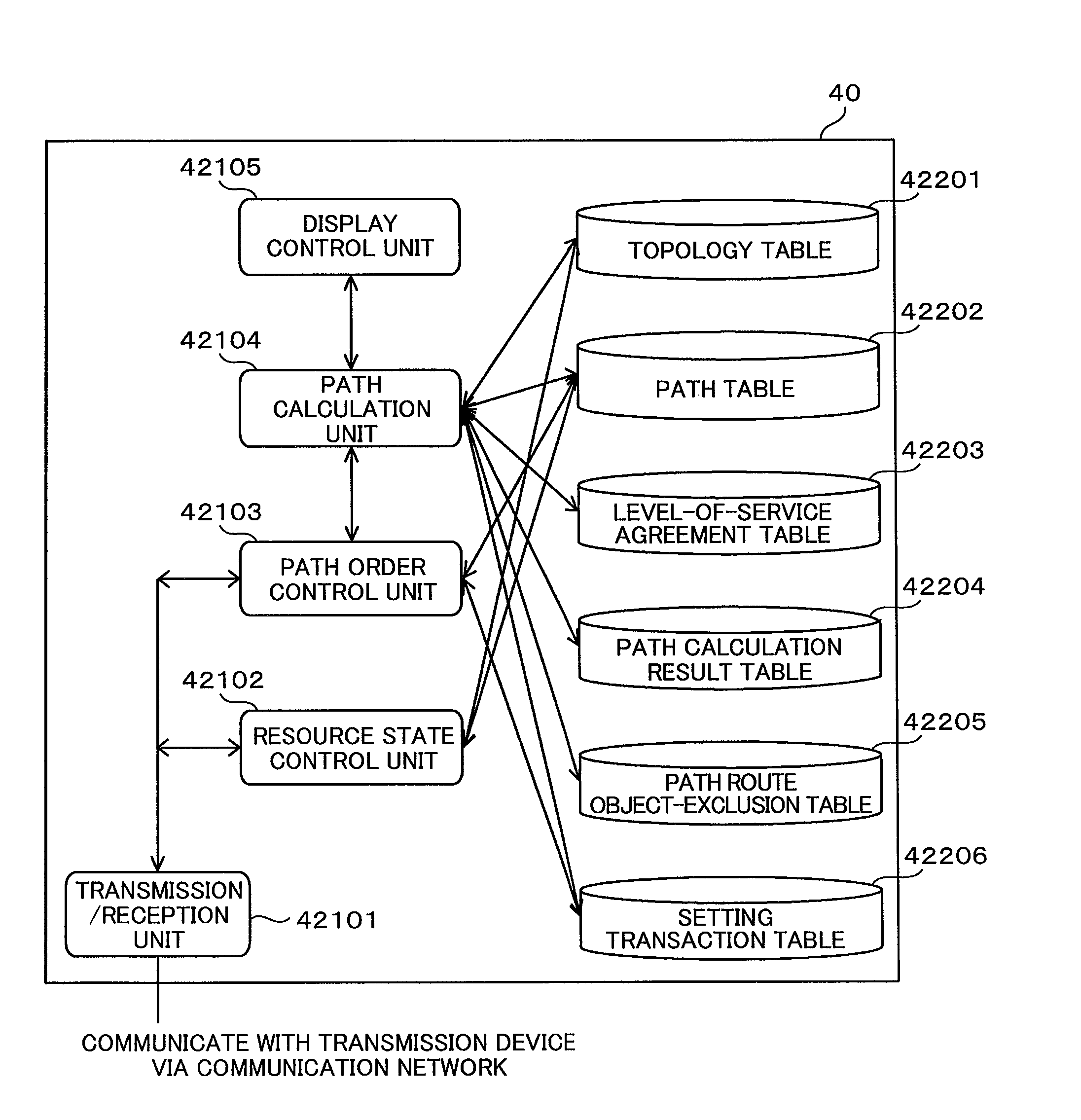
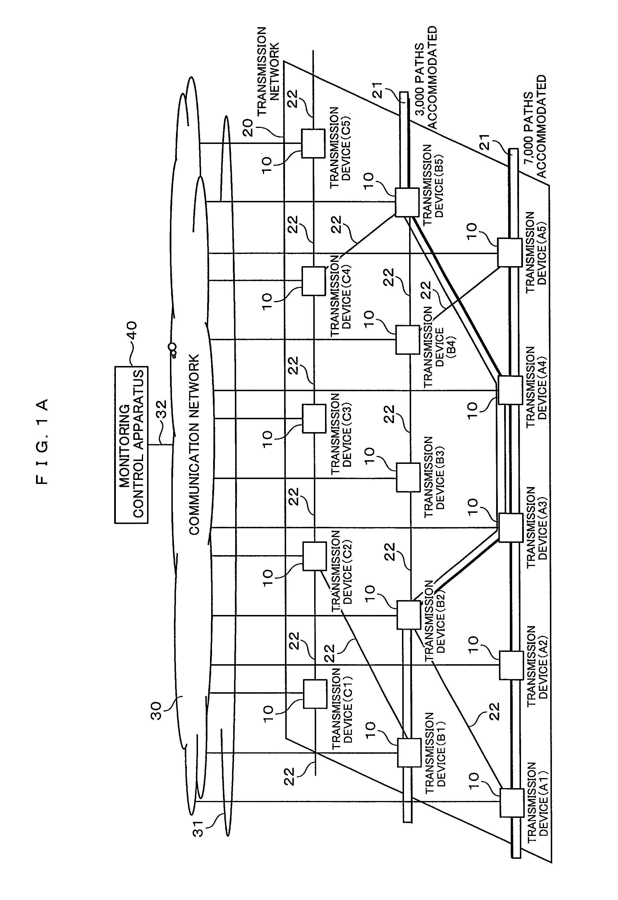
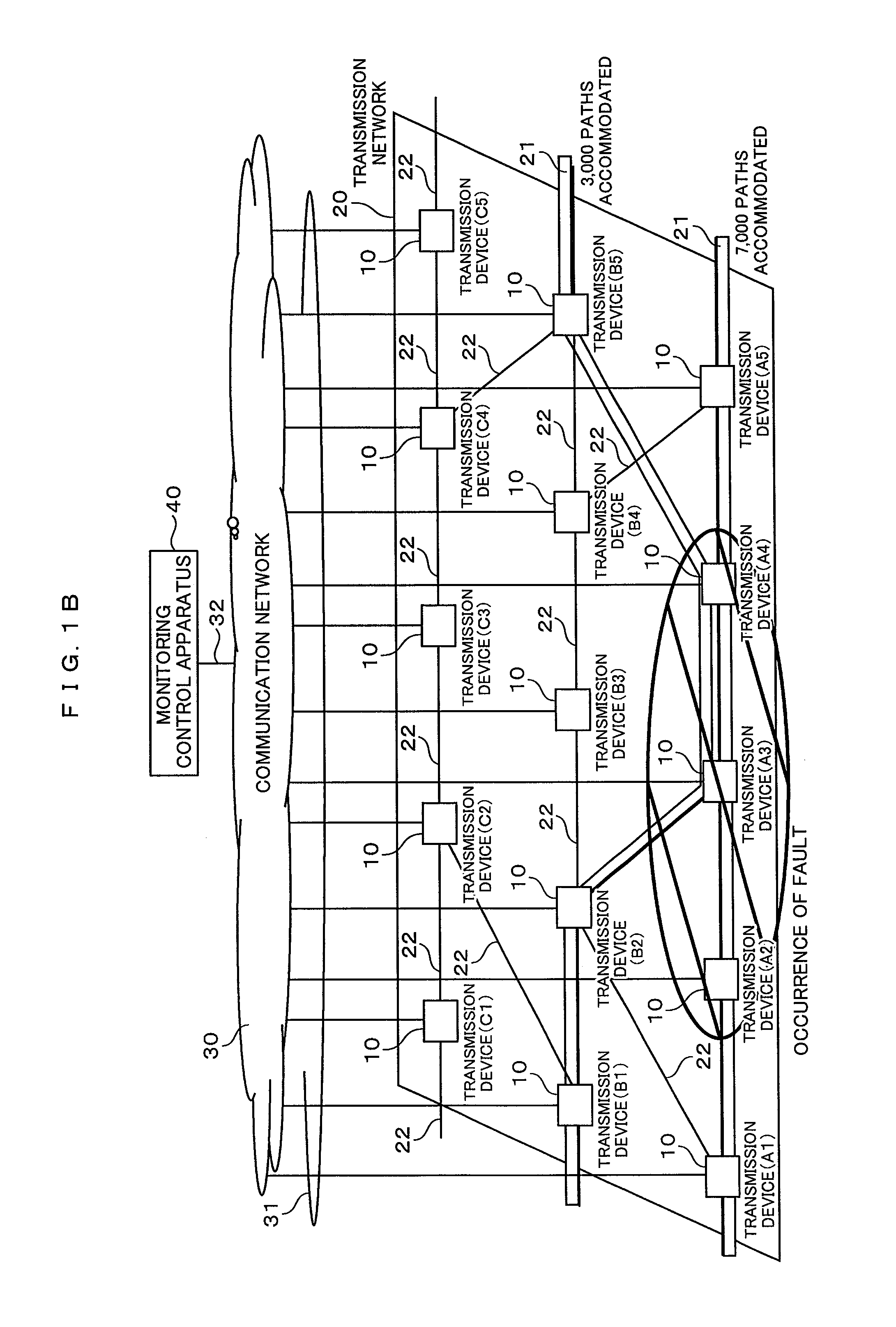
[0046]FIG. 1A is a diagram showing a configuration example of a system according to the present embodiment. The present system is composed of transmission devices 10, a transmission network 20, a communication network 30, and a monitoring control apparatus 40. The monitoring control apparatus 40 monitors the operations of a plurality of the transmission devices 10 included in the communication network 30, and the tra...


PUM


Abstract

A path table, a topology table and a level-of-service agreement table are stored in a storage device of a monitoring control apparatus. A path in which a communication fault occurs is determined based on the path table. The service levels small in terms of an upper limit value of a service cutoff time in emergency are sequentially extracted from the level-of-service agreement table. A path route calculation process is performed on at least one path coincident with the extracted service level, based on the path table. A path route optimization process is performed on at least one path route subjected to the route calculation. An execution result of the path route optimization process is registered in a path calculation result table.

Description

CLAIM OF PRIORITY[0001]The present application claims priority from Japanese application JP 2013-173520 filed on Aug. 23, 2013, the content of which is hereby incorporated by reference into this application.BACKGROUND OF THE INVENTION[0002]The present invention relates to a technology in which in a detour path setting method for a transmission device system, a monitoring control apparatus grasps a resource situation at the occurrence of a fault and calculates a detour path based on a level of service agreement in emergency to thereby perform a path setting.[0003]In general, in a transmission system, 1+1 path protection redundancy is constructed in preparation for service cutoff at the occurrence of a fault. This is a system in which when a fault occurs in an active system path that provides services, a line is switched to a reserve system path to continue services. There may however be a case where at a major fault such as at a serious disaster or the like, a fault simultaneously oc...

Claims


Application Information

Patent Timeline
Patent Type & Authority Applications(United States)
IPC IPC(8): H04L12/24H04L12/751H04L45/28H04L45/02
CPCH04L41/0668H04L41/12H04L45/02H04L41/5025H04L41/0659H04L45/22H04L45/28
Inventor CHAKI, NOBUYUKINONAKA, YASUMICHIKAMIYA, AKIHIRO
Owner HITACHI LTD
Why Eureka
Try Eureka