
Method for connecting battery cells in a battery, battery, and monitoring device

Inactive Publication Date: 2015-02-26
ROBERT BOSCH GMBH
View PDF7 Cites 8 Cited by
  • Summary
  • Abstract
  • Description
  • Claims
  • Application Information

AI Technical Summary

Benefits of technology

The present invention is about improving the way a battery's state of charge is determined. By adding a special battery cell with a lower capacity than a standard cell, the invention makes it easier to accurately determine the battery's state of charge during use. This helps prevent sudden drops in battery power. The method allows for the battery's state of charge to be measured even when it is almost fully discharged. The invention also includes a monitoring device that combines all components needed for better battery charge determination.

Problems solved by technology

However, since errors in current measurement resulting from integration continually add up, it is always necessary to compare this methodology with the state of charge calculated on the basis of the open circuit voltage.
So far, it has been very difficult to use these important systems in batteries, the state of charge of which must be estimated as precisely as possible, such as, for example, in a plug-in hybrid vehicle and an electric vehicle.
The aforementioned problems of determining the state of charge may, particularly near the end of a discharge, lead to a residual capacity being displayed in the battery management system, whereas the actual capacity of the battery is already fully spent.
Where the aforementioned cell chemistry systems are concerned, this problem may mean that such systems cannot be used in electric vehicles or in similar applications.

Method used


Image

  • Method for connecting battery cells in a battery, battery, and monitoring device
  • Method for connecting battery cells in a battery, battery, and monitoring device
  • Method for connecting battery cells in a battery, battery, and monitoring device

Examples


Embodiment Construction

[0039]In the following description of preferred exemplary embodiments of the present invention, identical or similar reference numerals are used for elements which are similarly operating elements and represented in the various figures, a repeated description of these elements being omitted.

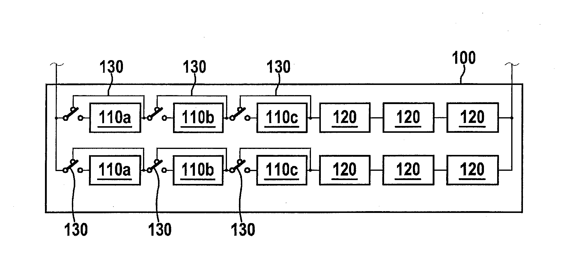
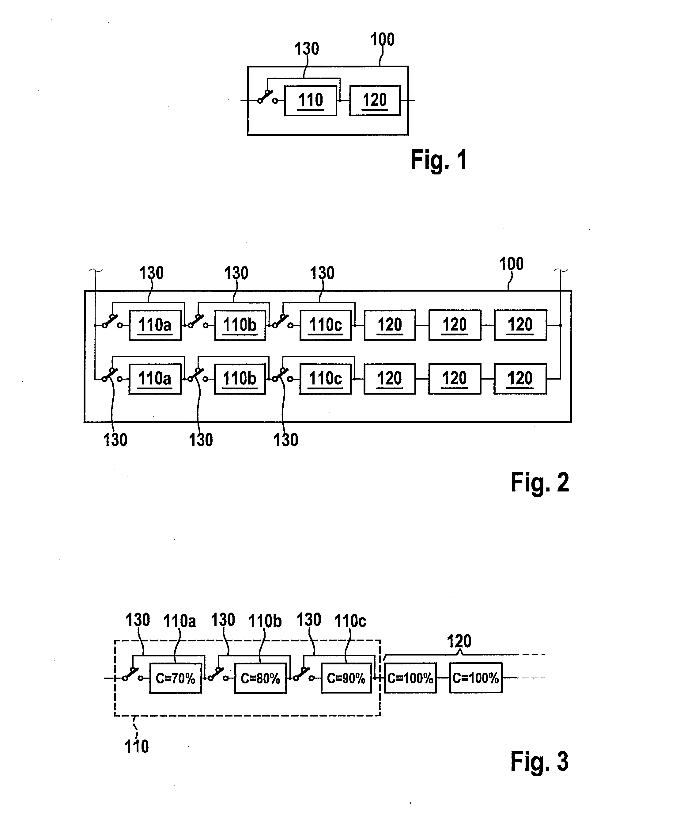
[0040]FIG. 1 shows a schematic representation of a battery according to one exemplary embodiment of the present invention. In a series connection in a battery 100 are a measuring battery cell 110 and a standard battery cell 120. Measuring battery cell 110 also includes a switchable bypass 130. The two terminals of the series connection are directed outwardly. The two terminals have opposite polarities. Switchable bypass 130 of measuring battery cell 110 is depicted in the switch position bypassing measuring battery cell 110.

[0041]In another exemplary embodiment, the number of measuring battery cells 110 and the number of standard battery cells 120 may be increased in the shown series connection o...


PUM


Abstract

A method for connecting battery cells in a battery is provided, the battery including at least one measuring battery cell and at least one standard battery cell in a series connection, the standard battery cell having at least a nominal capacity which is greater than a nominal capacity threshold, the measuring battery cell having a nominal capacity which is less than the nominal capacity threshold, the measuring battery cell having a switchable bypass, the method including: monitoring a state of charge of the at least one measuring battery cell; and bypassing the at least one measuring battery cell using the switchable bypass if the state of charge of the at least one measuring battery cell drops below a predefined state of charge threshold.

Description

BACKGROUND OF THE INVENTION[0001]1. Field of the Invention[0002]The present invention relates to a method for connecting battery cells in a battery, to a battery, to a corresponding monitoring device and to a corresponding computer program product.[0003]2. Description of The Related Art[0004]Normally, the state of charge (SOC) of a battery is determined by measuring the open circuit voltage at the entire battery or at individual cells. If at a particular time, a measurement is possible only under load, then the open circuit voltage may be calculated based on the measured voltage, the current flow and the resistance. This calculation may be corrected later, once a comparison with the measurement of the open circuit voltage (without load) is possible.[0005]In addition, the current flow into or out of the battery may be integrated, in order to obtain an indication of the state of charge. However, since errors in current measurement resulting from integration continually add up, it is a...

Claims


Application Information

Patent Timeline
IPC IPC(8): H01M10/48H01M10/052G01R31/36H01M50/51
CPCH01M10/48G01R31/3606H01M2220/20H01M10/052G01R31/3658H01M10/0525H01M10/441G01R19/16542Y02E60/10H01M50/51G01R31/382G01R31/396
Inventor POEHLER, JOERGTENZER, MARTIN
Owner ROBERT BOSCH GMBH
Learn More