Engine Crankcase Breathing Passage With Flow Diode

a technology of flow diodes and internal combustion engines, which is applied in the direction of combustion engines, crankcase ventillation, machines/engines, etc., can solve the problems of difficult control of back draining and breathing, high probability, and the creation of fine oil mist/droplets, so as to reduce power loss resonance, reduce the speed of flow, and the flow pattern is stable

Inactive Publication Date: 2015-03-05
GM GLOBAL TECH OPERATIONS LLC
View PDF3 Cites 36 Cited by
  • Summary
  • Abstract
  • Description
  • Claims
  • Application Information

AI Technical Summary

Benefits of technology

[0044]It should be noted that the mean velocity curve 802M, 902M for the conventional system is less than or equal to zero indicating an average flow in opposition to the oil draining direction. Furthermore, the maximum and minimum velocity curves 802H, 802L, 902H, 902L in the drain and breather lines of the conventional system show velocities of up to ±55 m / s around 6000 rpm indicating a back-and-forth flow pattern which hampers proper oil draining and crankcase ventilation. By comparison, the mean velocity curves 804M, 806M, 904M, 906M for the system with flow diodes is positive indicating an average flow in the oil draining direction. In addition, the maximum and minimum velocity curves 804H, 804L, 806H, 806L, 904H, 904L, 906H, 906L, in the drain and breather lines of the system with flow diodes show up to about 66% reduction in the velocities indicating a more stable flow pattern.
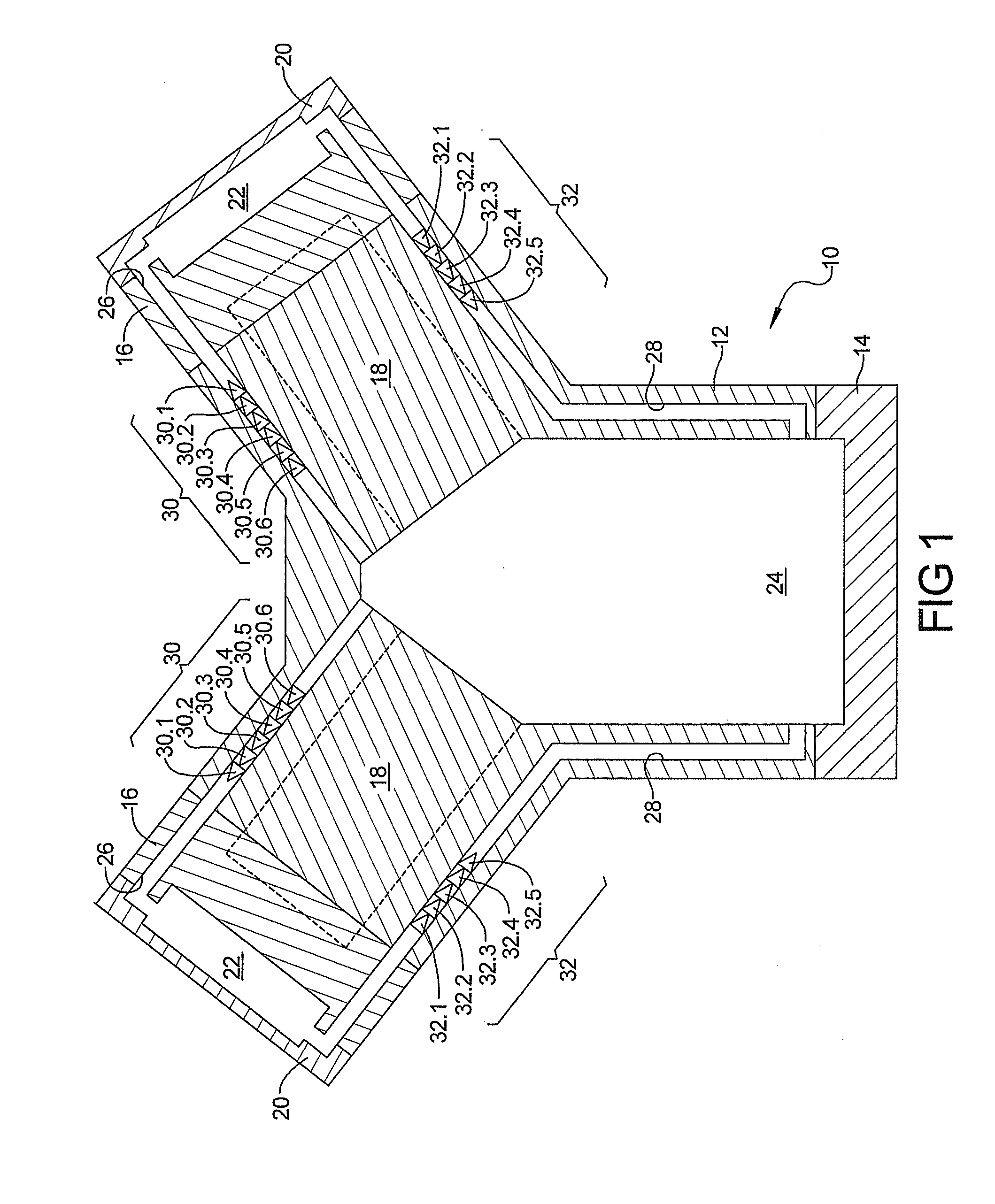
[0045]FIGS. 10A-10D show plots 1000, 1010, 1020, 1030 of the pressure amplitude (kPa) in the crankcase as a function of engine speed (rpm). The solid lines 1002, 1012, 1022, 1032 represent the pressure amplitude in crankcase bays #1-#4 respectively in a conventional system. The short dashed lines 1004, 1014, 1024, 1034 represent the pressure amplitude in crank bays #1-#4 respectively in a drain back system having flow diodes 30, 32 including flow diodes with a Q value of 2.3 in the breather and drain lines 26, 28. From these plots, it should be noted that the pressure resonance amplitudes observed in the peak power range (between 5000-7000 rpm) in the conventional system are drastically reduced by creating a direction of preferred flow with flow diodes 30, 32. Attenuating the crankcase resonances reduces power loss resonance in the peak power range. Additional power loss reduction is expected with a decrease in oil-to-air mass fraction associated with a drop in oil misting. Increasing the Q value of the flow diodes results in a larger decrease in the pressure amplitude at resonance. It is also important to note that the presence of the flow diodes has a minimal effect on the pressure amplitudes in the fuel economy (less than 3000 rpm) and mid-power (3000-5000 rpm) ranges.

Problems solved by technology

However, reciprocating engines often create a pulsating pressure differential in the crankcase which overrides the desired flow direction in the crankcase making drain back and breathing difficult to control.
Excessive oil may be retained in the valve covers and there is a highly likelihood that fine oil mist / droplets are created.
In addition to affecting drain back and breathing, conventional systems may create pressure waves in the crankcase which excite natural resonant frequencies of the engine, in the crankcase cavity or PCV system.
The interaction between the pressure waves and the engine components when driven at these resonant frequencies can reduce power output and generate unwanted noise and vibration from the engine.
These interactions will also hinder oil drain back and cause higher oil pullover into the intake region.

Method used


Image

  • Engine Crankcase Breathing Passage With Flow Diode
  • Engine Crankcase Breathing Passage With Flow Diode
  • Engine Crankcase Breathing Passage With Flow Diode

Examples


Embodiment Construction

[0023]Example embodiments will now be described more fully with reference to the accompanying drawings.

[0024]Example embodiments are provided so that this disclosure will be thorough, and will fully convey the scope of this disclosure to those who are skilled in the art. Specific details may be set forth to provide a thorough understanding of embodiments of the present disclosure. It will be apparent to those skilled in the art that specific details need not be employed, that example embodiments may be embodied in many different forms and that neither should be construed to limit the scope of the disclosure. In some example embodiments, well-known processes, well-known structures, and well-known technologies are not described in detail.

[0025]The terminology used herein is for the purpose of describing particular example embodiments only and is not intended to be limiting. As used herein, the singular forms “a,”“an,” and “the” may include the plural forms as well, unless the context ...


PUM


Abstract

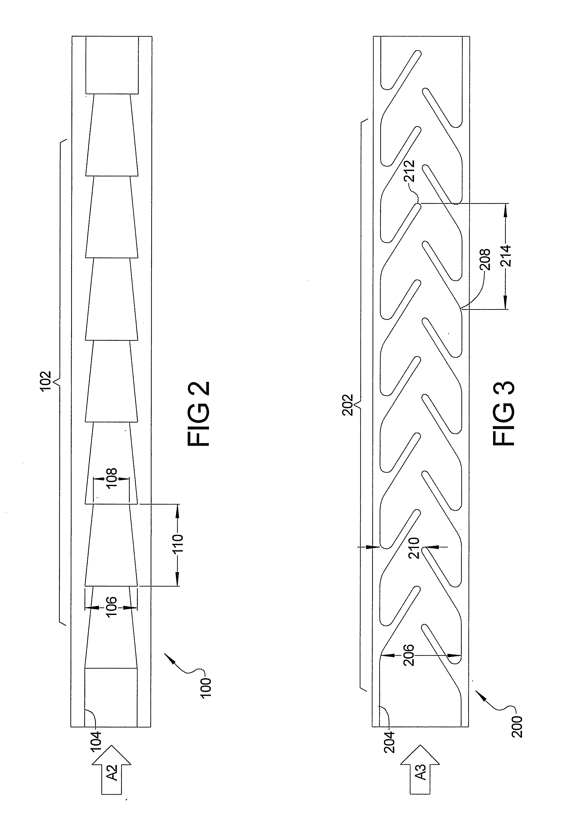
An internal combustion engine is disclosed which includes an improved crankcase drain back system. A set of drain flow diodes are disposed in each of the drain lines to direct fluid flow in a direction from the head portion to the crankcase. Likewise, a set of breather flow diodes are disposed in the breather lines to direct fluid flow in a second direction from the cylinder portion to the head portion. The flow diodes include a series of stacked flow diode elements which allow flow in one direction, while resisting flow in the opposite direction.

Description

FIELD[0001]The present disclosure relates to flow control for crankcase draining and breathing of an internal combustion engine, and more specifically to the use of flow diodes in the crankcase drain and breather passageways for generating flow in the direction of intended oil drain back and / or direction of intended breather flow.BACKGROUND[0002]This section provides background information related to the present disclosure which is not necessarily prior art.[0003]Under certain operating conditions gases from the cylinders of an internal combustion engine get past the piston rings and leak into the engine crankcase. These blow-by gases typical include intake air, unburned fuel, exhaust gas, oil mist and / or water vapor. It is desirable to ventilate the crankcase and re-circulate the blow-by gases to the intake side of the engine for combustion to enhance performance and improve emissions.[0004]To this end, conventional engine blocks have a series of breathers that allow the blow-by ga...

Claims


Application Information

Patent Timeline
Patent Type & Authority Applications(United States)
IPC IPC(8): F01M13/00
CPCF01M13/00F01M13/04F01M2013/0038
Inventor CLAYWELL, MARK R.PRYOR, BRYAN K.
Owner GM GLOBAL TECH OPERATIONS LLC
Why Eureka
Try Eureka