
Light emitting diode assembly and liquid crystal display device including the same

a technology of light-emitting diodes and liquid crystal displays, which is applied in the direction of optics, instruments, optical elements, etc., can solve the problems of reducing restricting the increase of leds, and shortening the life of leds, etc., and achieves the effects of narrow bezels, high brightness, and thin thickness

Inactive Publication Date: 2015-03-05
LG DISPLAY CO LTD
View PDF10 Cites 16 Cited by
  • Summary
  • Abstract
  • Description
  • Claims
  • Application Information

AI Technical Summary

Benefits of technology

This patent describes an LED assembly for a liquid crystal display device that allows for a thinner, narrower bezel, and higher brightness. Additionally, the LED assembly improves heat-discharging properties to increase the LED chips' lifetime, reduces bonding problems, simplifies manufacturing processes, and lowers manufacturing costs.

Problems solved by technology

However, since a length of the printed circuit board and a distance between the LEDs are fixed, there is a restriction on an increase of the LEDs.
Accordingly, when the heat is not properly discharged, there may be problems of degrading the LEDs, lowering the light efficiency and shortening the lifetime of the LEDs.

Method used


Image

  • Light emitting diode assembly and liquid crystal display device including the same
  • Light emitting diode assembly and liquid crystal display device including the same
  • Light emitting diode assembly and liquid crystal display device including the same

Examples


Embodiment Construction

[0029]Reference will now be made in detail to the preferred embodiments, examples of which are illustrated in the accompanying drawings.

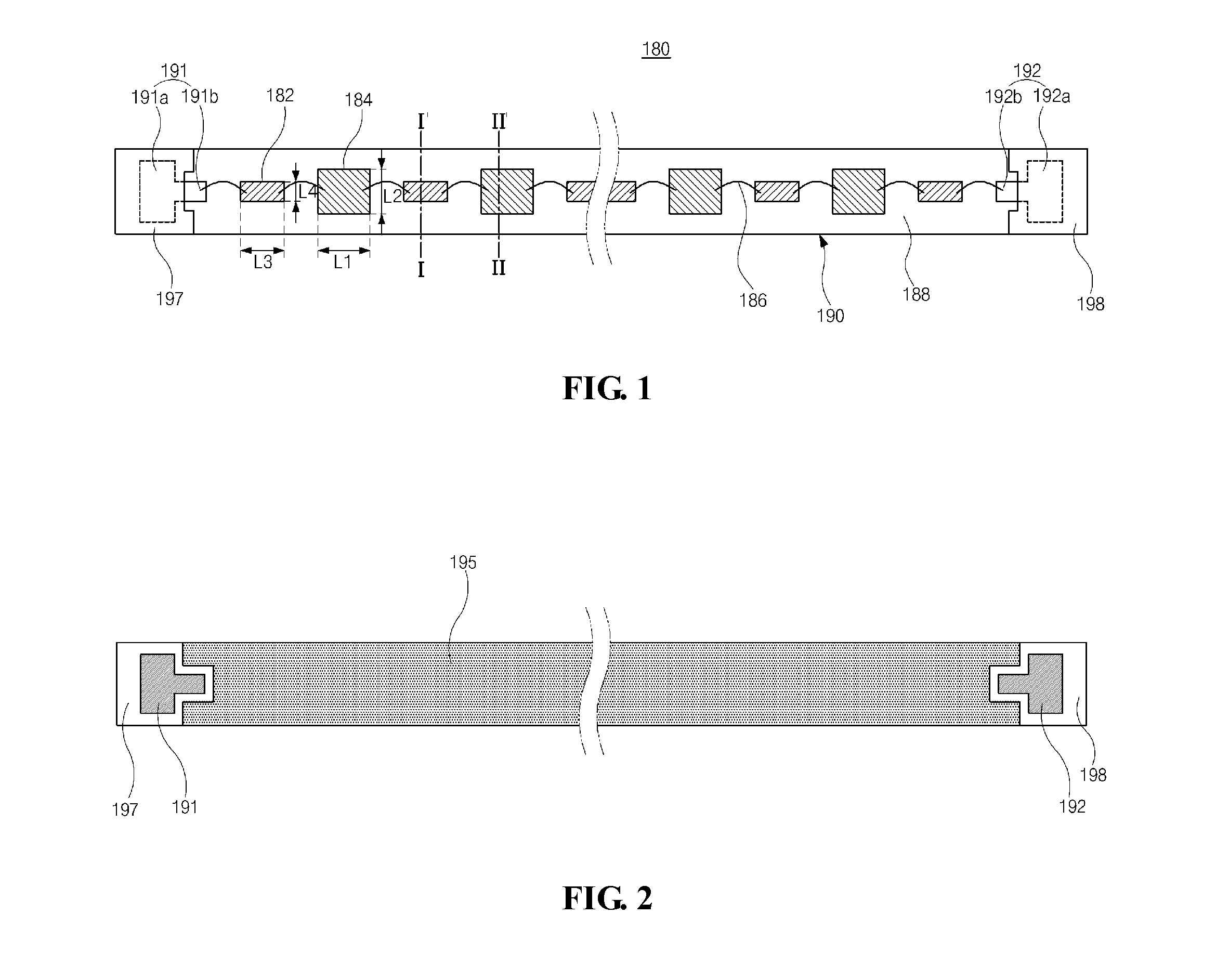
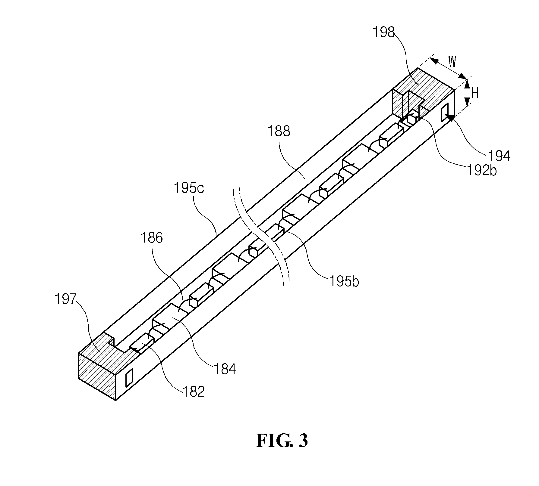
[0030]FIG. 1 is a plan view of illustrating an LED assembly according to an exemplary embodiment of the present invention, FIG. 2 is a rear view of illustrating the LED assembly of FIG. 1, and FIG. 3 is a perspective view of illustrating the LED assembly of FIG. 1.

[0031]In FIG. 1, FIG. 2 and FIG. 3, the LED assembly 180 includes LED chips 182 emitting light, connecting portions 184 for connection between the LED chips 182, wires 186 electrically connecting the LED chips 182 and the connecting portions 184, a sealing portion 188 sealing the LED chips 182 and the connecting portions 184, and a frame portion 190 surrounding the LED chips 182, the connecting portions 184, the wires 186 and the seal portion 188 to form one united body.

[0032]The LED chips 182 are arranged in the frame portion 190 along a length direction of the frame portion 190 in a line...


PUM

PropertyMeasurementUnit
fluorescentaaaaaaaaaa
conductiveaaaaaaaaaa
lengthaaaaaaaaaa

Abstract

A liquid crystal display device includes a liquid crystal panel; and a backlight unit disposed under the liquid crystal panel and including an LED assembly, wherein the LED assembly includes a frame portion, LED chips arranged in the frame portion in a line and spaced apart from each other, connecting portions each disposed between adjacent LED chips and connected to adjacent LED chips through wire bonding, and a sealing portion including a fluorescent substance and covering the LED chips and the connecting portions, and wherein the sealing portion changes light emitted from the LED chips into a linear light source.

Description

[0001]The present application claims the priority benefit of Korean Patent Application No. 10-2013-0103708 filed in the Republic of Korea on Aug. 30, 2013, which is hereby incorporated by reference in their entirety.BACKGROUND[0002]1. Field of the Disclosure[0003]The present disclosure relates to a light emitting diode assembly and a liquid crystal display device including the same, and more particularly, to a light emitting diode (LED) assembly and a liquid crystal display (LCD) device including the same that improve heat-discharging properties and have a narrow bezel and a slim thickness.[0004]2. Discussion of the Related Art[0005]Liquid crystal display (LCD) devices are widely used as monitors of notebook computers, monitors of personal computers and televisions due to excellent reproduction of moving images and high contrast ratio. LCD devices use the optical anisotropy and polarization properties of liquid crystal molecules of a liquid crystal layer to produce an image.[0006]An...

Claims


Application Information

Patent Timeline
Patent Type & Authority Applications(United States)
IPC IPC(8): G02F1/1335H01L27/15H01L33/62
CPCG02F1/133603H01L27/153H01L33/62G02F1/133606G02F1/133608G02F1/133607G02B6/0023G02B6/0073G02B6/0083H01L25/0753H01L33/50H01L2224/48091H01L2924/00014
Inventor LEE, ROK-HEESIM, JAE-MINKIM, DO-MAN
Owner LG DISPLAY CO LTD
Learn More