

Virtual image display apparatus
- Summary
- Abstract
- Description
- Claims
- Application Information
AI Technical Summary
Benefits of technology
Problems solved by technology
Method used
Image

Examples
example 1
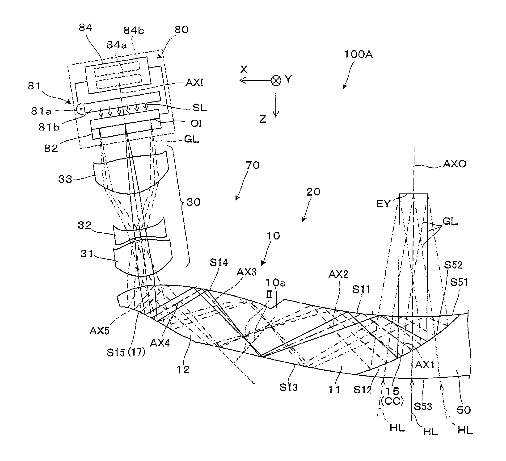
[0123]In a projection see-through device of Example 1, data on an optical surface constituting a light guide member and a projection lens is shown in Table 1. For example, FFS1 means the first surface S11, FFS2 means the second surface S12, and FFS3 means the third surface S13. Furthermore, ASP1 means an emission surface of a first lens of the projection lens, and ASP2 means an incidence surface of the first lens.
TABLE 1NoTypeRTNdVd1SPH∞20.002FFS1—5.501.52555.953FFS2—−5.501.52555.954FFS1—10.001.52555.955FFS3—−20.001.52555.956FFS4—10.001.52555.957FFS5—−10.001.52555.958FFS4—−0.509ASP1−6.137−6.001.52555.9510ASP26.711−0.5011ASP36.613−1.201.58529.9012ASP4−17.825−6.0013ASP5−7.024−6.001.52555.9514ASP632.129−3.9115SPH∞−1.601.45867.8216imagesurface
[0124]In regard to the optical surface in the light guide member constituting Example 1, the optical axis inclination angle (tilt) TLY on the cross section and the optical axis deviation amount (decenter) DCX are shown in Table 2. As for the fourth...
example 2
[0133]In a projection see-through device of Example 2, data on an optical surface constituting a light guide member and a projection lens is shown in Table 5.
TABLE 5NoTypeRTNdVd1SPH∞22.002FFS1—5.501.52555.953FFS2—−5.501.52555.954FFS1—10.001.52555.955FFS3—−20.001.52555.956FFS4—14.001.52555.957FFS5—−10.001.52555.958FFS6—−2.009ASP1−20.674−7.001.52555.9510ASP29.056−0.5011ASP37.190−1.001.58529.9012ASP454.244−19.3713ASP5−10.384−8.151.52555.9514ASP6−23.928−4.9815SPH∞−1.601.45867.8216imagesurface
[0134]In regard to the optical surface in the light guide member constituting Example 2, the optical axis inclination angle (tilt) TLY on the cross section and the optical axis deviation amount (decenter) DCX are shown in Table 6.
TABLE 6TLY (beforeDCX (afterTLY (afterNoTypesurface)surface)surface)2FFS10003FFS2−290294FFS10005FFS3024.171−39.586FFS4500507FFS5−500−508FFS6000
[0135]In regard to each optical surface in the light guide member constituting Example 2, the coefficient in polynomial expression ...
example 3
[0141]In a projection see-through device of Example 3, data on an optical surface constituting a light guide member and a projection lens is shown in Table 9.
TABLE 9NoTypeRTNdVd1SPH∞20.002FFS1—5.501.52555.953FFS2—−5.501.52555.954FFS1—9.001.52555.955FFS3—−17.001.52555.956FFS4—7.001.52555.957FFS5—2.001.52555.958ASP17.6974.001.52555.959ASP2−4.9070.5010ASP3−5.1581.501.58529.9011ASP45.2762.8412ASP56.5016.001.52555.9513ASP6−10.1929.5114SPH∞1.601.45867.8215imagesurface
[0142]In regard to the optical surface in the light guide member constituting Example 3, the optical axis inclination angle (tilt) TLY on the cross section and the optical axis deviation amount (decenter) DCX are shown in Table 10.
TABLE 10TLY (beforeDCX (afterTLY (afterNoTypesurface)surface)surface)2FFS10003FFS2−260264FFS10005FFS3019.893504−29.3946226FFS4600607FFS5000
[0143]In regard to each optical surface in the light guide member constituting Example 3, the coefficient in polynomial expression of a free-form surface is show...
PUM
 Abstract
Description
Claims
Application Information