
System and method for measuring force and torque applied to a catheter electrode tip

a technology of force and torque and catheter electrode tip, which is applied in the field of system and method for assessing force and torque, can solve the problems of catheter tip perforation or other damage to tissue, variety and even death, and ineffective lesions created

Inactive Publication Date: 2015-03-12
ST JUDE MEDICAL ATRIAL FIBRILLATION DIV
View PDF4 Cites 19 Cited by
  • Summary
  • Abstract
  • Description
  • Claims
  • Application Information

AI Technical Summary

Benefits of technology

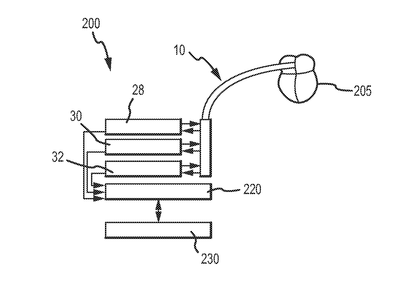
The patent describes a system for assessing the degree of coupling between an electrode and tissue in the body, such as cardiac tissue. The system includes a contact sensing assembly that includes a catheter and an electrode. The electrode has a tip portion and a base portion mounted adjacent the head portion of the catheter body. The system includes one or more sensors that measure pressure or torque applied to the electrode tip portion and provide an output signal related to the measured pressure or torque. The system can determine the degree of coupling between the electrode and tissue based on the measured pressure or torque. The system can also include a plurality of sensors that provide a vector reconstruction of the net tip contact force using a vector addition algorithm or relationship. The system can be used for diagnostic or therapeutic purposes and can automatically limit the force applied to the electrode tip. The system can also provide feedback to a practitioner regarding the tissue contact force and can warn of a high or unacceptable force, a loss of contact force, or a too low force.

Problems solved by technology

Arrhythmia can create a variety of dangerous conditions including irregular heart rates, loss of synchronous atrioventricular contractions and stasis of blood flow which can lead to a variety of ailments and even death.
If the electrode is too far from the tissue or has insufficient contact with the tissue, the lesions created may not be effective.
On the other hand, if the catheter tip containing the electrode contacts the tissue with excessive force, the catheter tip may perforate or otherwise damage the tissue (e.g., by overheating).
Each of these methods has disadvantages, however.
The determination is particularly difficult when using catheters that are relatively long (such as those used to enter the left atria of the heart).
Because fluoroscopic images are two-dimensional projections and blood and myocardium attenuate x-rays similarly, it can be difficult to quantify the degree of contact force and detect when the catheter tip is not in contact with the tissue.
Intracardiac echo can be time consuming and it can be difficult to align the echo beam with the ablation catheter.
Further, intracardiac echo does not always permit the clinician to confidently assess the degree of contact and can generate unacceptable levels of false positives and false negatives in assessing whether the electrode is in contact with tissue.
Atrial electrograms do not always correlate well to tissue contact and are also prone to false negatives and positives.
Pacing thresholds also do not always correlate well with tissue contact and pacing thresholds can be time-consuming and also prone to false positives and negatives because tissue excitability may vary in hearts with arrhythmia.
Evaluating lesion size at necropsy is seldom available in human subjects, provides limited information (few data points) and, further, it is often difficult to evaluate the depth and volume of lesions in the left and right atria.
Finally, temperature measurements provide limited information (few data points) and can be difficult to evaluate in the case of irrigated catheters.

Method used


Image

  • System and method for measuring force and torque applied to a catheter electrode tip
  • System and method for measuring force and torque applied to a catheter electrode tip
  • System and method for measuring force and torque applied to a catheter electrode tip

Examples


Embodiment Construction

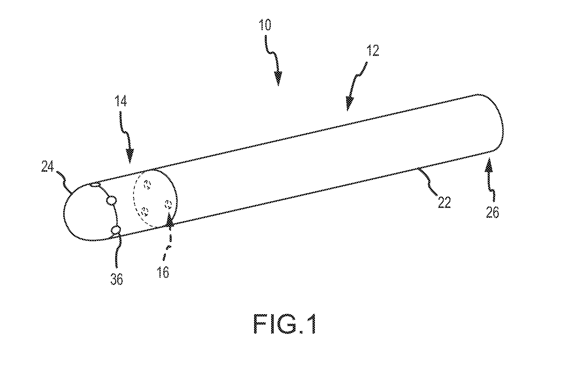
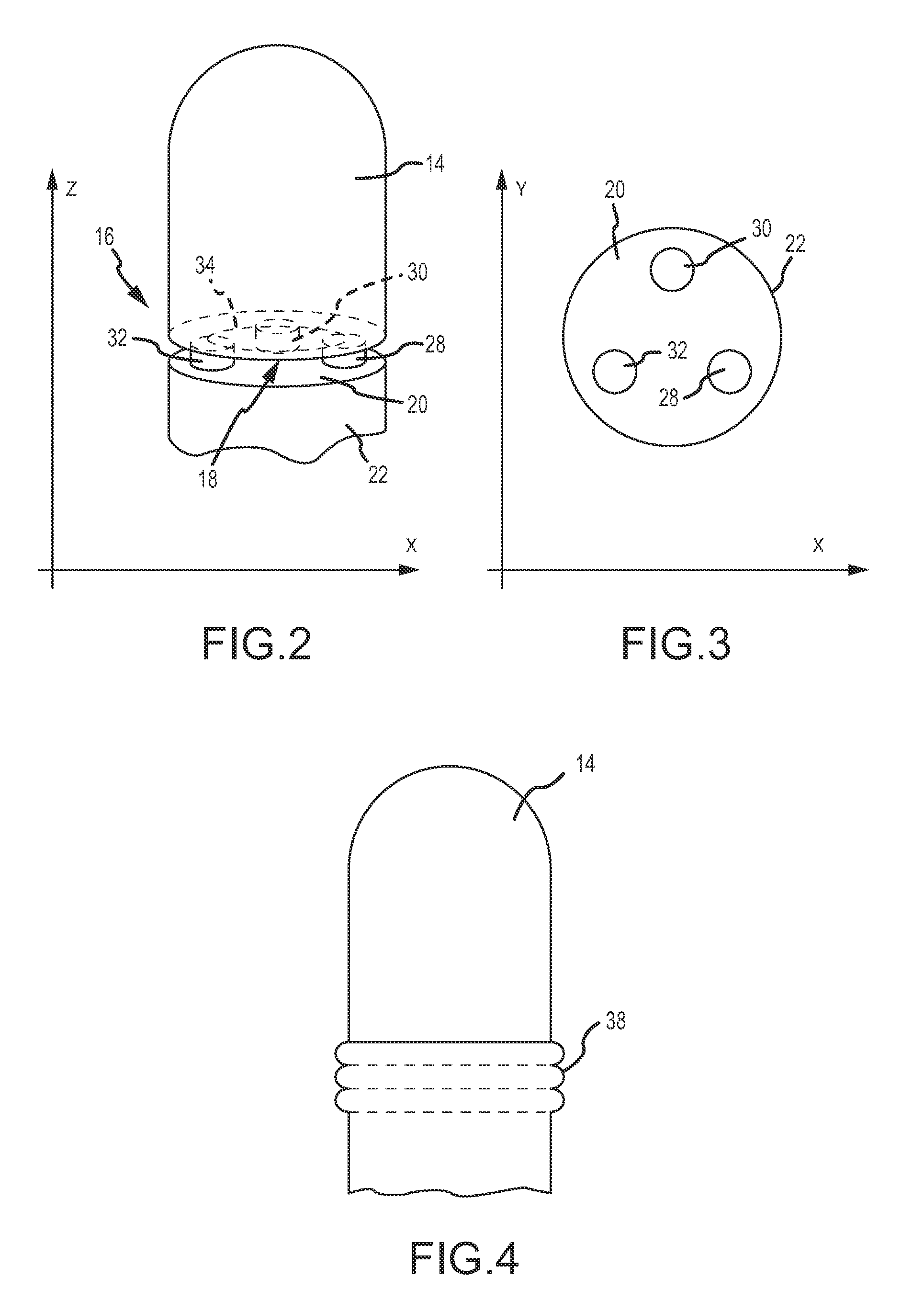
[0032]Referring now to the drawings wherein like reference numerals are used to identify like components in the various views, FIG. 1 illustrates an exemplary embodiment of a contact sensing assembly 10 as provided by the invention. In a general form, referring to FIGS. 1 and 2, contact sensing assembly 10 may include a catheter 12, an electrode 14 connected to the catheter, and a force and torque sensor 16 for interacting with base 18 of electrode 14 or alternatively with head 20 of catheter body 22 if sensor 16 is mounted on base 18. In another embodiment, contact sensing assembly 10 may include a first interactive component and a second interactive component. The contact sensing assembly may be used in the diagnosis, visualization, and / or treatment of tissue (such as endocardial tissue) in a body. Contact sensing assembly 10 may be used in a number of diagnostic and therapeutic applications, such as for example, the recording of electrograms in the heart, the performance of cardi...


PUM


Abstract

A contact sensing assembly including a catheter including an electrode having a base portion mounted adjacent a head portion of the catheter body. A sensor is disposed adjacent the base portion for measuring compression or tensile forces applied to an electrode tip portion, and includes a predetermined sensitivity. The base and head portions include predetermined rigidity so that forces applied to the electrode tip portion are determinable as a function of the sensitivity and a sensor output. A contact sensing assembly also includes an electrode pipe operatively connected to the catheter body for movement and bending with the catheter body, and an electrode wire disposed in the electrode pipe and including isolation. A change in capacitance resulting from movement of the electrode wire toward the electrode pipe or contact of the electrode wire with the electrode pipe during bending of the catheter correlates to a force applied to the catheter.

Description

CROSS-REFERENCE TO RELATED APPLICATIONS[0001]This application is a continuation of U.S. application Ser. No. 12 / 347,607, filed 31 Dec. 2008, now pending, which is hereby incorporated by reference as though fully set forth herein.BACKGROUND OF THE INVENTION[0002]a. Field of the Invention[0003]This invention relates to a system and method for assessing the force and torque between an electrode and tissue in a body. In particular, the instant invention relates to a system and method for assessing the force and torque between an electrode tip on a diagnostic and / or therapeutic medical device such as a mapping or ablation catheter and tissue, such as cardiac tissue. The instant invention also relates to a method for sensing and calculating contact force exerted by another component on a tissue, and generally, a method for sensing and calculating contact force on an elongate member when in contact with another component or structure, for medical or non-medical purposes.[0004]b. Background...

Claims


Application Information

Patent Timeline
Patent Type & Authority Applications(United States)
IPC IPC(8): A61B5/00A61N1/05A61B8/12A61B18/14A61B5/042
CPCA61B5/6885A61B18/1492A61B5/042A61B8/12A61B2218/002A61B18/02A61B18/24A61B2019/465A61N7/022A61N1/05A61B2090/065A61B5/283
Inventor KLIMOVITCH, GLEB V.SLIWA, JOHN W.
Owner ST JUDE MEDICAL ATRIAL FIBRILLATION DIV
Learn More