Electric power steering device

a technology of electric power steering and steering shaft, which is applied in the direction of bearing unit rigid support, gearing, hoisting equipment, etc., can solve the problems of backlash sound generation, and achieve the effects of improving steering feeling, preventing leaf spring impedance, and improving steering feeling in fine steering

Inactive Publication Date: 2015-03-19
JTEKT CORP
View PDF18 Cites 24 Cited by
  • Summary
  • Abstract
  • Description
  • Claims
  • Application Information

AI Technical Summary

Benefits of technology

[0015]According to the first aspect of the invention, the sliding contact surface of the synthetic resin member which is disposed on the outer periphery of the second bearing is in contact with the leaf spring, and therefore it is possible to prevent the leaf spring from impeding the axial movement of the worm. Consequently, the axial movement of the worm which is urged to the axial neutral position by the pair of elastic members is performed very smoothly, so that, also in fine steering in which the worm does not receive a driving force, the play due to the internal clearances of the bearings can be surely eliminated, and the steering feeling can be improved.
[0016]Particularly, the frictional force between the leaf spring and the sliding contact surface of the synthetic resin member is smaller than that between the leaf spring and the housing, and therefore it is possible to surely prevent the leaf spring held by the housing, from impeding the axial movement of the worm.
[0017]Furthermore, the pair of elastic members which are placed on the both sides of the first bearing urge the worm in the axial directions, and the leaf spring which surrounds the second bearing surrounds the periphery of the second bearing, and causes the worm to swing. In the type in which the function of urging the worm in the axial directions, and that of urging the worm in a radial direction (toward the worm wheel) are placed in the both ends of the worm, respectively, namely, the steering feeling in fine steering can be improved.
[0018]According to the second aspect of the invention, axial crowning is applied to the sliding contact surface of the synthetic resin member, and therefore a sufficient swing amount can be ensured when the worm is caused to swing by a reverse input from the road surface. Consequently, the prying of the worm can be prevented from occurring. Moreover, the crowning can reduce the contact area of the sliding contact surface of the synthetic resin member with respect to the leaf spring, and therefore the swinging and axial movement of the worm can be performed more smoothly. Moreover, the contact is formed between the sliding contact surface having a crowning shape, and the cylindrical surface, and therefore the smoothness of the swinging and axial movement of the worm can be attained at a low cost.
[0019]According to the third aspect of the invention, a resultant force in the circumferential whole area of the open-ended annular main body portion which surrounds the outer periphery of the second bearing (outer periphery of the synthetic resin member) urges the second bearing in a direction of separating from the worm wheel. On the other hand, the pair of elastic tongue pieces urge the second bearing in two directions which are inclined oppositely to each other toward the worm wheel, through the corresponding rotation limiting portions. Namely, the second bearing is urged in the three directions by the leaf spring. With respect to play in a lateral direction (direction perpendicular to the directions in which the center-to-center distance between the worm and the worm wheel is increased and decreased), therefore, the movement of the second bearing can be easily suppressed. Consequently, an abnormal sound due to play of the second bearing and the bearing holding hole of the housing can be prevented from being generated.
[0020]According to the fourth aspect of the invention, the low-friction resin layer is disposed on the outer periphery of the second bearing, and therefore the frictional resistance between the housing hole and the low-friction resin layer or that between the interposing member and the low-friction resin layer can be reduced. Consequently, the axial movement of the worm which is axially urged by the pair of elastic members that are on the both sides of the first bearing is performed very smoothly, so that, also in fine steering in which the worm does not receive a driving force, the play due to the internal clearances of the two bearings can be surely eliminated, and the steering feeling can be improved. Moreover, a shock in a reverse input from the road surface can be buffered by the low-friction resin layer.

Problems solved by technology

During traveling, however, there is a possibility that a rattle sound due to backlash may be generated.

Method used


Image

  • Electric power steering device
  • Electric power steering device
  • Electric power steering device

Examples


first embodiment

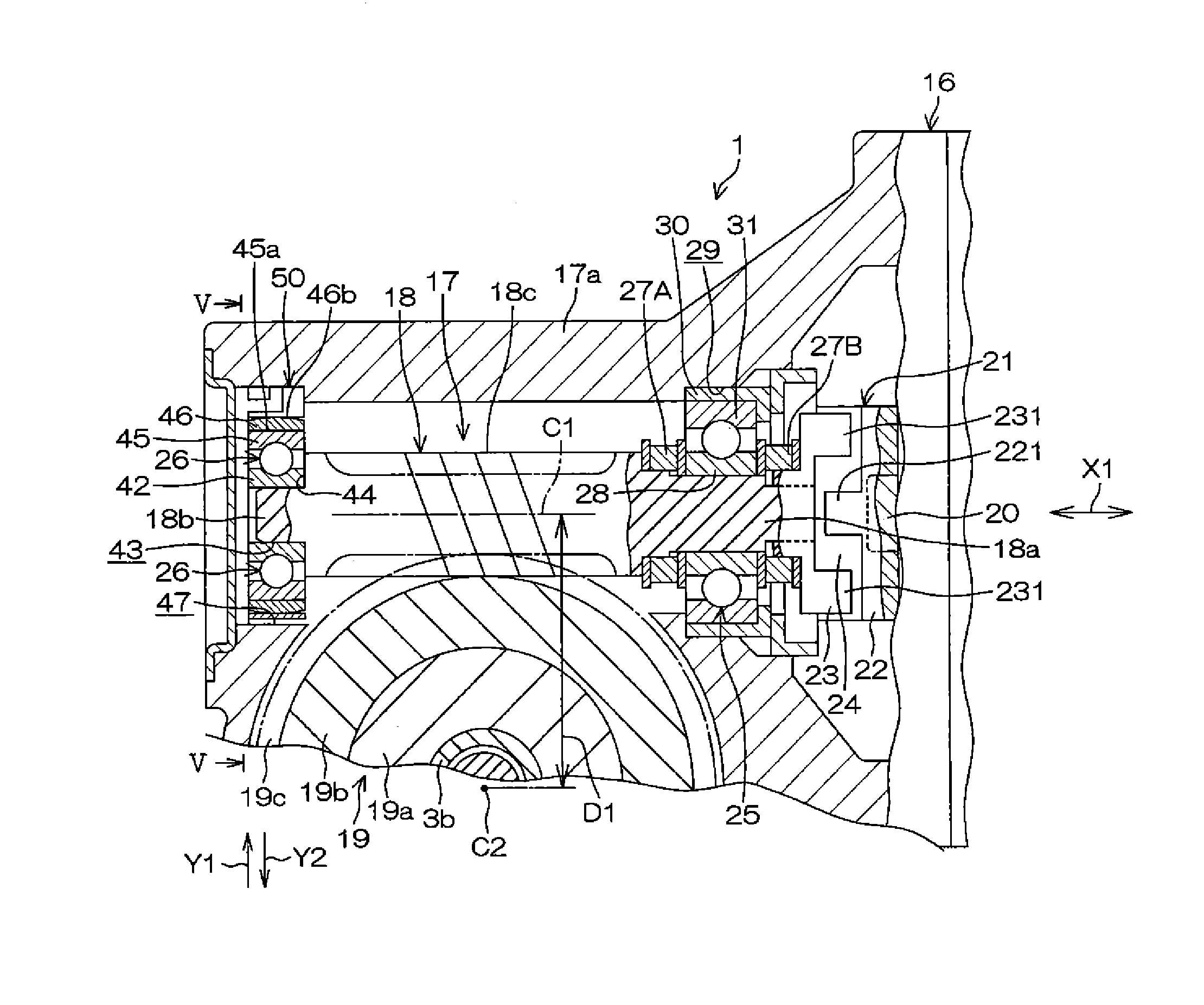
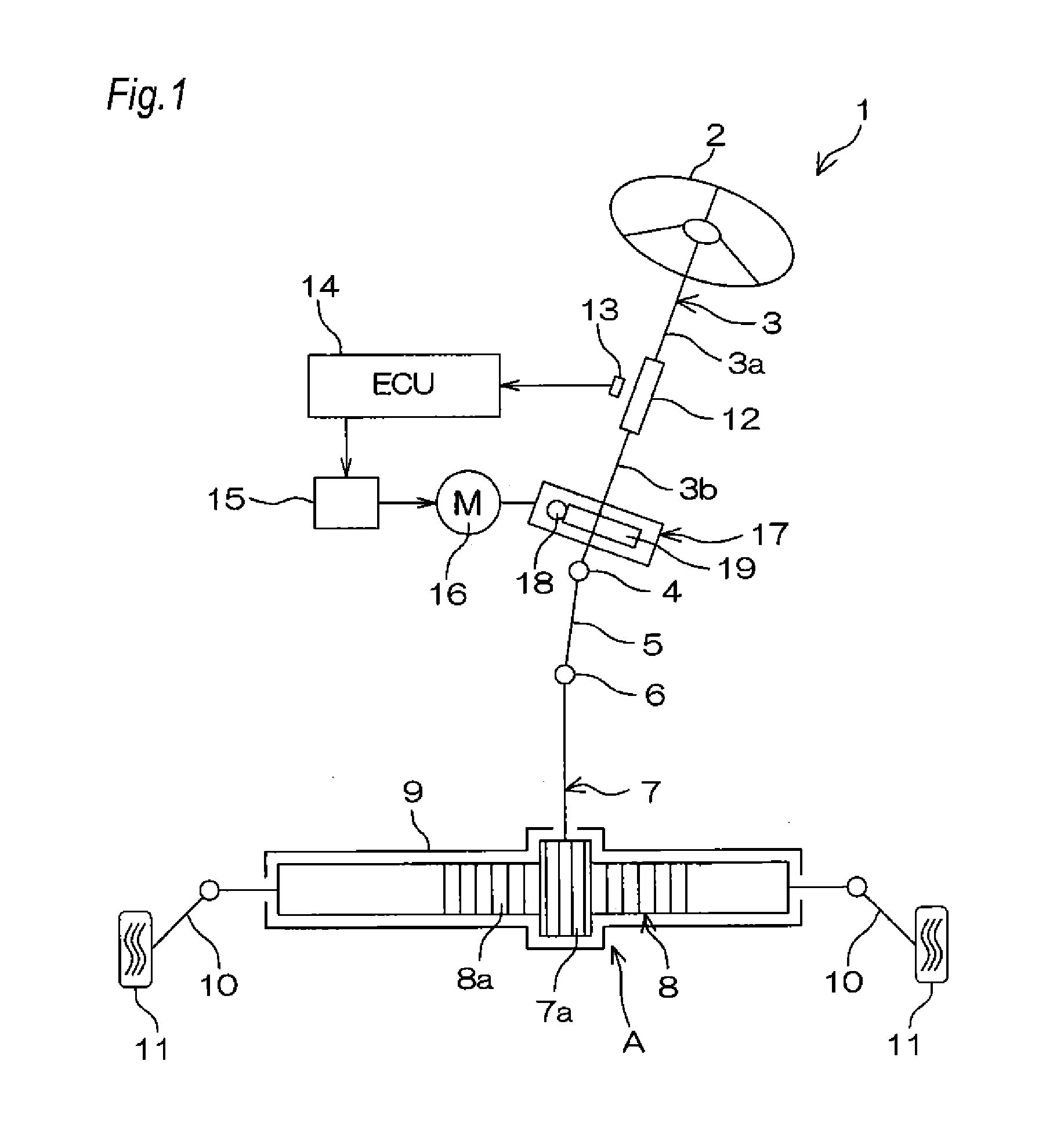
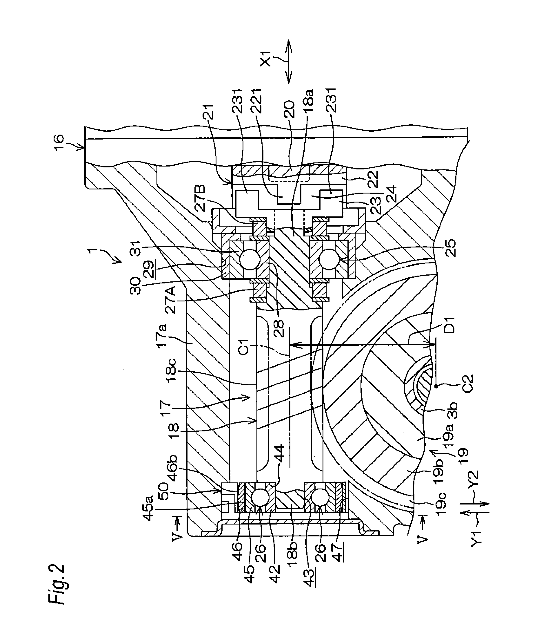
[0034]FIG. 1 is a schematic view of an electric power steering device of a Referring to FIG. 1, the electric power steering device 1 has: a steering shaft 3 which is connected to a steering member 2 such as a steering wheel; an intermediate shaft 5 which is connected to the steering shaft 3 through a universal joint 4; a pinion shaft 7 which is connected to the intermediate shaft 5 through a universal joint 6; and a rack bar 8 which has a rack 8a meshing with a pinion 7a disposed in the vicinity of an end portion of the pinion shaft 7, and which serves as a steerable shaft extending in the right-and-left direction of an automobile. The pinion shaft 7 and the rack bar 8 constitute a steering mechanism A configured by a rack-and-pinion mechanism.

[0035]The rack bar 8 is supported in a housing 9 fixed to the vehicle body, so as to be linearly reciprocable, through a plurality of bearings (not shown). Both end portions of the rack bar 8 are projected toward the both sides of the housing...

second embodiment

[0068]FIG. 7 is a schematic view of an electric power steering device of a Referring to FIG. 7, the electric power steering device 101 has: a steering shaft 103 which is connected to a steering member 102 such as a steering wheel; an intermediate shaft 105 which is connected to the steering shaft 103 through a universal joint 104; a pinion shaft 107 which is connected to the intermediate shaft 105 through a universal joint 106; and a rack bar 108 which has a rack 108a meshing with a pinion 107a disposed in the vicinity of an end portion of the pinion shaft 107, and which serves as a steerable shaft extending in the right-and-left direction of an automobile. The pinion shaft 107 and the rack bar 108 constitute a steering mechanism A2 configured by a rack-and-pinion mechanism.

[0069]The rack bar 108 is supported in a housing 109 fixed to the vehicle body, so as to be linearly reciprocable, through a plurality of bearings (not shown). Both end portions of the rack bar 108 are projected...


PUM


Abstract

An electric power steering device includes a worm which is swingably connected to the rotation shaft of an electric motor through a joint. A first end portion and second end portion of the worm are supported by a first bearing and a second bearing, respectively. A pair of elastic members elastically urge the worm to an axial neutral position. An annular leaf spring which is held by a housing urges the second end portion toward a worm wheel through the second bearing. A synthetic resin member having a sliding contact surface which is in contact with the leaf spring is integrally disposed on the second bearing.

Description

TECHNICAL FIELD[0001]The present invention relates to an electric power steering device.BACKGROUND ART[0002]In an electric power steering device, the output of an electric motor is reduced in speed through a worm and a worm wheel, and then transmitted to a steering mechanism, thereby assisting the torque of the steering operation.[0003]Backlash is required in meshing between a worm and a worm wheel. During traveling, however, there is a possibility that a rattle sound due to backlash may be generated.[0004]Conventionally, therefore, an electric power steering device has been proposed in which a bearing for supporting a worm is elastically urged toward a worm wheel to eliminate backlash.[0005]A technique has been proposed in which, is such an electric power steering device of the type in which a bearing for supporting a worm is elastically urged toward a worm wheel to eliminate backlash, the bearing for supporting the worm is axially preloaded to eliminate play of the bearing, whereb...

Claims


Application Information

Patent Timeline
Patent Type & Authority Applications(United States)
IPC IPC(8): F16H55/24B62D5/04B62D3/04
CPCF16H55/24B62D5/0403B62D3/04F16H1/16F16C19/06F16C27/08B62D5/0409F16C35/077F16C23/082F16C25/083F16C27/066F16H2057/0213F16H2057/02082F16H57/12F16H2057/127F16C2326/24F16C2380/27F16C2361/61Y10T74/19623F16C23/08
Inventor KIKUCHI, ARATAKUSANO, HIROTSUGUFUKUMOTO, YASUTAKA
Owner JTEKT CORP
Why Eureka
Try Eureka